
On-line monitoring management system for carbon emission of thermal power generating unit

A thermal power unit, monitoring and management technology, applied in the general control system, control/regulation system, computer control, etc., can solve the problem of affecting the credibility of enterprise carbon emission accounting data, affecting the design of carbon trading mechanism, carbon market transaction management, and comparability To improve immediacy and authenticity, shorten data flow routes, and reduce manual intervention

Inactive Publication Date: 2019-04-02
JIANGSU FRONTIER ELECTRIC TECH +2
View PDF4 Cites 10 Cited by
  • Summary
  • Abstract
  • Description
  • Claims
  • Application Information

AI Technical Summary

Problems solved by technology

At present, the carbon emission accounting of domestic power generation enterprises uniformly adopts the emission factor method. However, due to the differences in the quality of different fuel types and the combustion efficiency of units, the scales of emission factors and related parameters selected by power generation enterprises are different, resulting in poor comparability and directly affecting The credibility of corporate carbon emission accounting data, which in turn affects the design of carbon trading mechanisms and the management of carbon market transactions
[0004] Moreover, the carbon emission accounting data of the emission factor method is based on the year, which cannot reflect the actual level of unit carbon emission in a timely manner.
In addition, the carbon emission accounting method of the emission factor method needs to be estimated by using unit activity data such as fuel consumption and desulfurizer consumption provided by power generation companies, and fuel quality analysis data such as low calorific value and carbon content per unit calorific value. Quality and reliability cannot be guaranteed, which in turn affects the accuracy and timeliness of carbon emission accounting data for power generation companies

Method used


Image

  • On-line monitoring management system for carbon emission of thermal power generating unit
  • On-line monitoring management system for carbon emission of thermal power generating unit
  • On-line monitoring management system for carbon emission of thermal power generating unit

Examples


Embodiment Construction

[0044] The following description and drawings illustrate specific embodiments of the invention sufficiently to enable those skilled in the art to practice them. Other embodiments may incorporate structural, logical, electrical, process, and other changes. The examples merely represent possible variations. Individual components and functions are optional unless explicitly required, and the order of operations may vary. Portions and features of some embodiments may be included in or substituted for those of other embodiments. The scope of embodiments of the present invention includes the full scope of the claims, and all available equivalents of the claims.

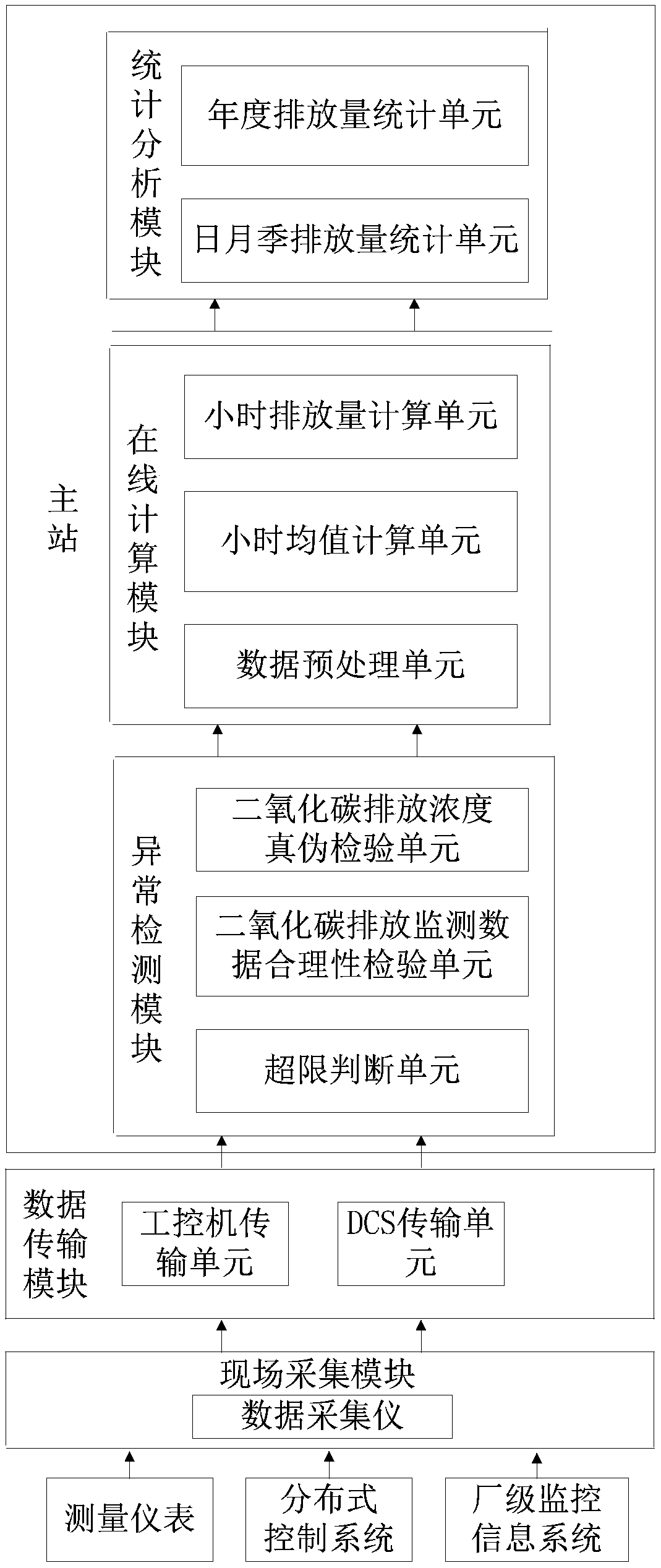
[0045] like figure 1 As shown, in some illustrative embodiments, an online carbon emission monitoring and management system for thermal power units is provided, which can not only obtain the carbon emission data of thermal power units in a timely and effective manner, improve the reliability of carbon emission data, but ...


PUM


Abstract

The invention provides an on-line monitoring management system for the carbon emission of a thermal power generating unit. The carbon dioxide generation and emission process key parameter of the thermal power generating unit can be subjected to real-time online monitoring, field monitoring data is subjected to online detection, an early warning is given for exceptional data in the field monitoringdata, and the reliability of carbon emission monitoring data is improved. On the basis, a thermal power generating unit carbon emission accounting model based on the field monitoring data is established, the carbon dioxide emission load of the thermal power generating unit is subjected to online calculation and statistical analysis, and timely and reliable thermal power generating unit carbon emission data is provided for a relevant government department to construct a carbon emission trading market.

Description

technical field [0001] The invention belongs to the technical field of carbon emission monitoring, and in particular relates to an online monitoring and management system for carbon emission of a thermal power unit. Background technique [0002] The power industry has been a major source of CO2 emissions due to the combustion of thermal coal. Since 2011, my country has proposed to build a carbon trading market to encourage greenhouse gas emitting enterprises to reduce carbon dioxide emissions and achieve carbon emission reduction goals at a lower cost. [0003] The carbon emission trading market is an effective means to achieve energy conservation and emission reduction by setting the total amount of carbon emission allowances and trading emission allowances. Greenhouse gas emissions data. At present, the carbon emission accounting of domestic power generation enterprises uniformly adopts the emission factor method. However, due to the differences in the quality of differe...

Claims


Application Information

Patent Timeline
IPC IPC(8): G05B19/048
CPCG05B19/048
Inventor 周春蕾孙和泰孙栓柱王明孙彬高进王其祥沈洋张友卫许国强周志兴佘国金肖明成魏威陈晨孟嘉
Owner JIANGSU FRONTIER ELECTRIC TECH
Learn More