Y-shaped micro-nano structure
A micro-nano structure and rectangular technology, applied in the field of micro-nano optics, can solve the problems of weak circular dichroism and high requirements for detection instruments, and achieve the effect of less absorption and dissipation and greater absorption and dissipation
- Summary
- Abstract
- Description
- Claims
- Application Information
AI Technical Summary
Problems solved by technology
Method used
Image

Examples
Embodiment 1
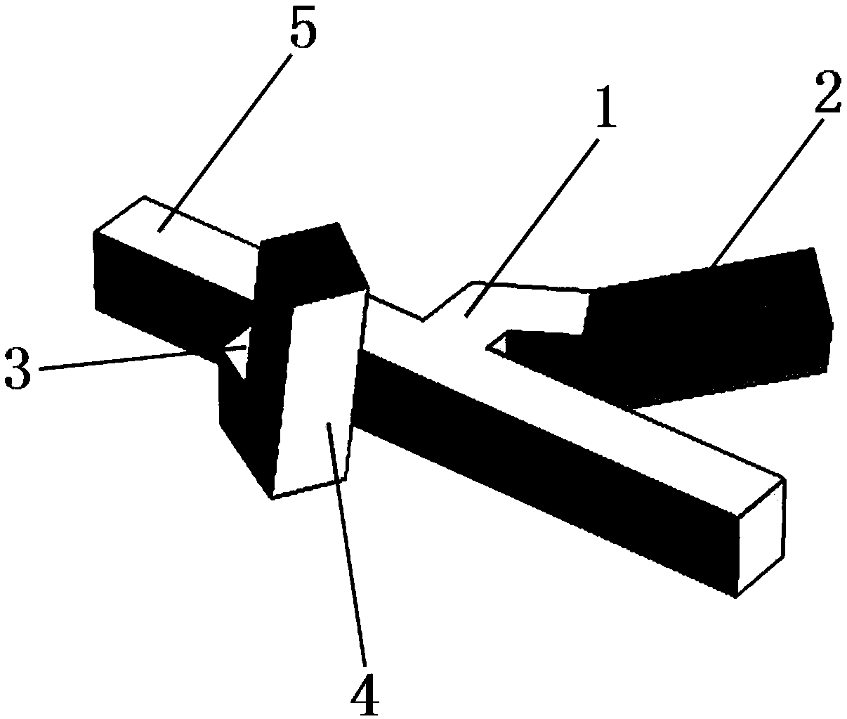
[0023] Such as figure 1 As shown, this embodiment discloses a Y-shaped micro-nano structure, including a rectangular rod 5, a first rectangular bar 1 and a second rectangular bar 2,
[0024] One end of the first rectangular bar 1 is vertically connected to one side of the rectangular bar 5, and the other end is connected with a second rectangular bar 2; there is an included angle not equal to 180° between the first rectangular bar 1 and the second rectangular bar 2, and the third One end of the rectangular bar 3 is vertically connected to the other side of the rectangular bar 5, and the other end is connected with a fourth rectangular bar 4; there is an included angle not equal to 180° between the third rectangular bar 3 and the fourth rectangular bar 4, and the second rectangular bar The end of the bar 2 is bent and has a first characteristic angle α with the plane where the rectangular rod 5 is located, and the end of the fourth rectangular bar 4 is bent and has a second cha...
Embodiment 2
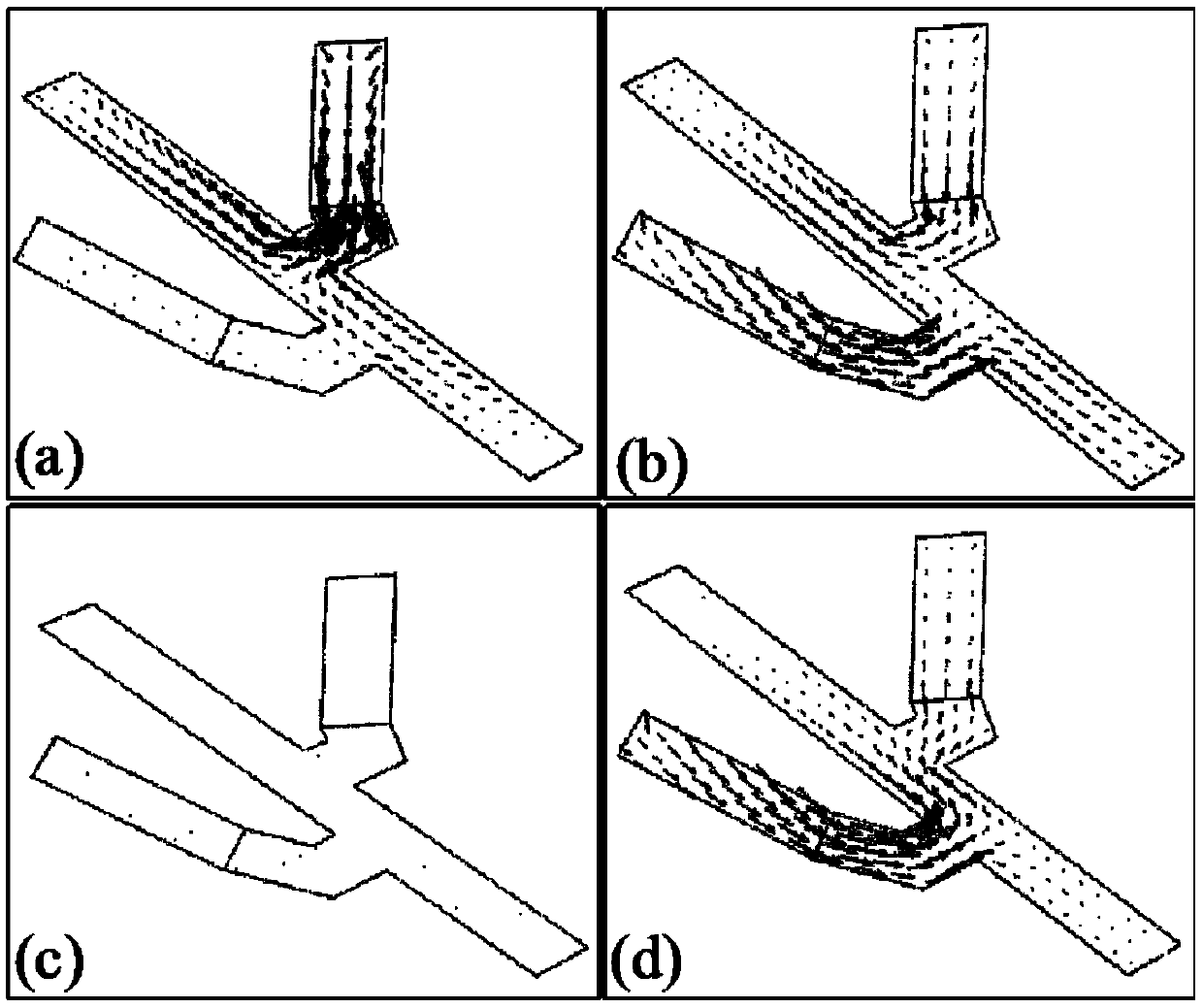
[0035] Based on the Y-shaped micro-nano structure disclosed in Example 1, this embodiment further discloses the current diagram and absorption spectrum diagram when the first characteristic angle α is equal to 15° and the second characteristic angle β is equal to 75°.
[0036] Such as image 3 Shown is the current distribution diagram of the micro-nano structure of this embodiment.
[0037] image 3 (a) is the current distribution diagram of the micro-nano structure irradiated by the left-handed polarized light of the wavelength λ=1100nm mode, image 3 (b) is a current distribution diagram of the micro-nano structure of this embodiment irradiated by right-handed polarized light with a wavelength of λ=1100 nm. image 3 (c) is the current distribution diagram of the micro-nano structure irradiated by the left-handed polarized light of the wavelength λ=1350nm mode, image 3 (d) is a current distribution diagram of the micro-nano structure of this embodiment irradiated by right...
Embodiment 3
[0047] Based on a Y-shaped micro-nano structure disclosed in Embodiment 1, on the basis of Embodiment 1, this embodiment is provided with a fifth rectangular strip opposite to the second rectangular strip 2 on the first rectangular strip 1, and the third rectangular strip 3 is provided with a sixth rectangular strip opposite to the fourth rectangular strip 4 . It is used to enhance the coupling between the rectangular strips, thereby generating a stronger excitation electric field, enhancing absorption, and thereby enhancing circular dichroism.
[0048] In particular, a through hole is provided on the rectangular rod 5 . The micro-nano structure of this embodiment is made of noble metal materials, and through holes are set on the rectangular rods 5, so as to guide and change the circulation mode of the current, thereby leading to different electric field couplings, thereby changing the circular dichroism of this embodiment. In addition, the through hole is filled with a phase...
PUM
 Abstract
Description
Claims
Application Information
 - R&D
- Intellectual Property
- Life Sciences
- Materials
- Tech Scout
- Unparalleled Data Quality
- Higher Quality Content
- 60% Fewer Hallucinations
Browse by: Latest US Patents, China's latest patents, Technical Efficacy Thesaurus, Application Domain, Technology Topic, Popular Technical Reports.
© 2025 PatSnap. All rights reserved.Legal|Privacy policy|Modern Slavery Act Transparency Statement|Sitemap|About US| Contact US: help@patsnap.com