
Anti-condensation structure for electric power distribution cabinet

A power distribution cabinet and anti-condensation technology, which is applied in the substation/distribution device casing, electrical components, substation/switch layout details, etc. Achieving the effect of high in-place rate

Active Publication Date: 2019-03-29
清远电力规划设计院有限公司 +1
View PDF8 Cites 4 Cited by
  • Summary
  • Abstract
  • Description
  • Claims
  • Application Information

AI Technical Summary

Problems solved by technology

[0005] The purpose of the present invention is to provide an anti-condensation structure for a power distribution cabinet to solve the problem that the existing device only filters and heats the air, and the degree of dehumidification of the air is not high enough. rusty damage problem

Method used


Image

  • Anti-condensation structure for electric power distribution cabinet
  • Anti-condensation structure for electric power distribution cabinet
  • Anti-condensation structure for electric power distribution cabinet

Examples


Embodiment

[0031] as attached figure 1 To attach Figure 6 Shown:

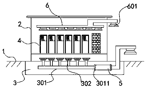
[0032] The invention provides an anti-condensation structure for a power distribution cabinet. The anti-condensation structure for a power distribution cabinet includes a ground 1, a pit 3 and a power distribution cabinet 2; There is a power distribution cabinet 2, the interior of the power distribution cabinet 2 is fixedly connected with a distribution device 4, the upper part of the power distribution cabinet 2 is fixedly connected with an exhaust duct 6, and the other side of the exhaust duct 6 is nested with an induced draft fan 601;

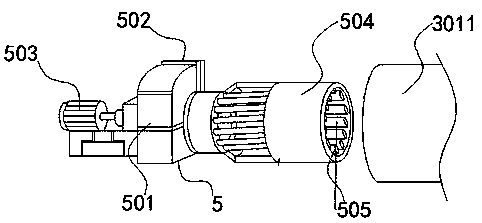
[0033] The inside of the pit 3 is fixedly connected with an air inlet pipe 301, and the other side of the air inlet pipe 301 extends to the outside of the pit 3. The air inlet pipe 301 is embedded with an air inlet 302, and the middle part of the air inlet pipe 301 is embedded with a cover plate 3011 and Dehumidification mechanism 5.

[0034] Wherein, the inner side and the bottom o...


PUM


Abstract

The invention provides an anti-condensation structure for an electric power distribution cabinet. The structure includes a ground surface, a ground pit, and the electric power distribution cabinet. Alower opening of the ground surface is provided with the ground pit; the electric power distribution cabinet is fixedly connected above the ground pit; a distributor is fixedly connected inside the electric power distribution cabinet; an air exhausting pipeline is fixedly connected to the upper side of the inside of the p electric power distribution cabinet; and an induced draft fan is nested on the other side of the air exhausting pipeline. The structure arranges wind teeth to be trumpet-shaped, when the wind teeth rotate at a high speed, water on the wind teeth is subjected to centrifugal force to move toward one side of a first ring moving plate, a water outlet and a flow guiding groove are arranged in a run-through manner, and the flow guiding groove can discharge water after air drying to the water outlet, so that the arrival rate is higher when a device is used, damage to the device cannot be due to the water.

Description

technical field [0001] The invention relates to the technical field, in particular to an anti-condensation structure for a power distribution cabinet. Background technique [0002] The power distribution cabinet is the final equipment of the power distribution system. The power distribution cabinet is the general name of the motor control center. The power distribution cabinet is used in occasions where the load is relatively scattered and there are few circuits. The motor control center is used in occasions where the load is concentrated and there are many circuits. , they distribute the electric energy of a certain circuit of the upper-level power distribution equipment to the nearby load, and this level of equipment should provide protection, monitoring and control for the load; [0003] Because of the internal heating of the traditional power distribution cabinet, it is necessary to cool down the inside and dissipate heat. However, due to the large temperature difference...

Claims


Application Information

Patent Timeline
Patent Type & Authority Applications(China)
IPC IPC(8): H02B1/28H02B1/56
CPCH02B1/28H02B1/565
Inventor 郑安靖
Owner 清远电力规划设计院有限公司
Learn More