Chemical ionization source based on novel reagent ions and self-calibration
A chemical ionization source and molecular ionization technology, applied in the field of ionization sources, can solve problems such as pollution and instrument instability, achieve the effects of improving ionization efficiency, improving collision paths, and solving instrument instability
- Summary
- Abstract
- Description
- Claims
- Application Information
AI Technical Summary
Problems solved by technology
Method used
Image
Examples
Embodiment 1
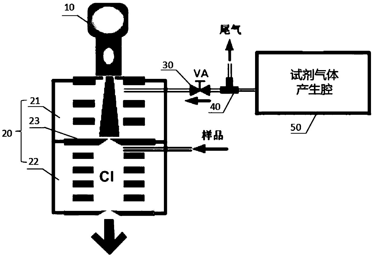
[0037] The chemical ionization source of the present invention is based on a novel reagent ion and a self-calibrating chemical ionization source for ionizing sample molecules to generate sample ions suitable for mass spectrometry analysis.
[0038] figure 1 is a schematic structural diagram of a chemical ionization source according to an embodiment of the present invention. Such as figure 1 As shown, the embodiment of the present invention provides a chemical ionization source, which includes a light source 10 and an ionization chamber 20 . Wherein, the ionization chamber 20 includes: a reagent ion generation area 21 , a sample molecule ionization area 22 and a light-shielding hole electrode 23 arranged between the reagent ion generation area 21 and the sample molecule ionization area 22 .
[0039] The reagent ion generation area 21 is arranged on the side of the ionization chamber 20 close to the light source 10, and coaxial multi-sheet electrodes are arranged in it; The r...
Embodiment 2
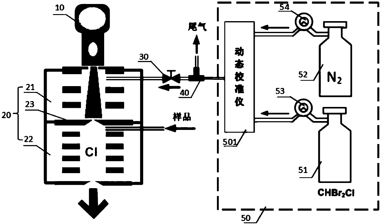
[0047] figure 2 It is a schematic structural diagram of a chemical ionization source according to this embodiment. The chemical ionization source of embodiment 2 is improved on the basis of embodiment 1, and its difference lies in: through feedback adjustment, the concentration of reagent molecules is controlled, so that the generated The concentration of reagent ions is kept constant.
[0048] Specifically, such as figure 2 As shown, the reagent gas generating chamber 50 includes a dynamic calibrator 501, a high-concentration reagent molecular standard gas chamber 51, a high-purity nitrogen gas chamber 52, a reagent gas speed regulating valve 53, and a nitrogen gas speed regulating valve 54; the high-concentration reagent molecular standard gas chamber 51 One inlet of the dynamic calibrator 501 is connected via a reagent gas speed regulating valve 53 , and the high-purity nitrogen chamber 52 is connected to the other inlet of the dynamic calibrator 501 via a nitrogen speed...
Embodiment 3
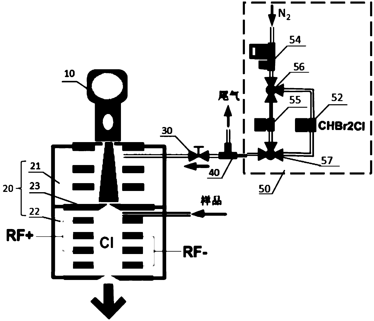
[0052] image 3 It is a schematic structural diagram of a chemical ionization source according to this embodiment. The chemical ionization source of embodiment 3 is improved on the basis of embodiment 1. The difference is that the chemical ionization source also includes a radio frequency voltage generator, The radio frequency voltage generator connects multiple electrodes in the sample molecule ionization region 22 and applies a radio frequency electric field to the sample molecule ionization region 22 .
[0053] Further, the multiple electrodes in the sample molecule ionization region 22 include a positive ionization electrode located on one side of the irradiation path of the light source 10 and a negative ionization electrode located on the other side of the irradiation path of the light source 10 . The first pole (RF+) of the radio frequency voltage generator is connected to the positive ionization electrode, and the second pole (RF-) of the radio frequency voltage genera...
PUM
 Abstract
Description
Claims
Application Information
 - R&D
- Intellectual Property
- Life Sciences
- Materials
- Tech Scout
- Unparalleled Data Quality
- Higher Quality Content
- 60% Fewer Hallucinations
Browse by: Latest US Patents, China's latest patents, Technical Efficacy Thesaurus, Application Domain, Technology Topic, Popular Technical Reports.
© 2025 PatSnap. All rights reserved.Legal|Privacy policy|Modern Slavery Act Transparency Statement|Sitemap|About US| Contact US: help@patsnap.com


