
Tilting transmission device for fixing engine

A transmission device and engine technology, which is applied in the direction of power device, power device arrangement/installation, aircraft power transmission, etc., can solve the problems of increasing the difficulty of engine design and certification, and reduce the difficulty of development, design and certification The effect of difficulty

Inactive Publication Date: 2019-03-29
CHINA HELICOPTER RES & DEV INST
View PDF6 Cites 6 Cited by
  • Summary
  • Abstract
  • Description
  • Claims
  • Application Information

AI Technical Summary

Problems solved by technology

In this way, it is necessary to verify the operation of the engine at different angles, which increases the difficulty of engine design and evidence collection

Method used


Image

  • Tilting transmission device for fixing engine
  • Tilting transmission device for fixing engine
  • Tilting transmission device for fixing engine

Examples


Embodiment Construction

[0028] In order to make the objectives, technical solutions and advantages of the implementation of the application clearer, the technical solutions in the implementation modes of the application will be described in more detail below with reference to the drawings in the implementation modes of the application. In the drawings, the same or similar reference numerals denote the same or similar elements or elements having the same or similar functions throughout. The described embodiments are some, but not all, embodiments of the present application. The embodiments described below by referring to the figures are exemplary and are intended to explain the present application, and should not be construed as limiting the present application. Based on the implementation manners in this application, all other implementation manners obtained by persons of ordinary skill in the art without creative efforts shall fall within the scope of protection of this application. Embodiments of ...


PUM


Abstract

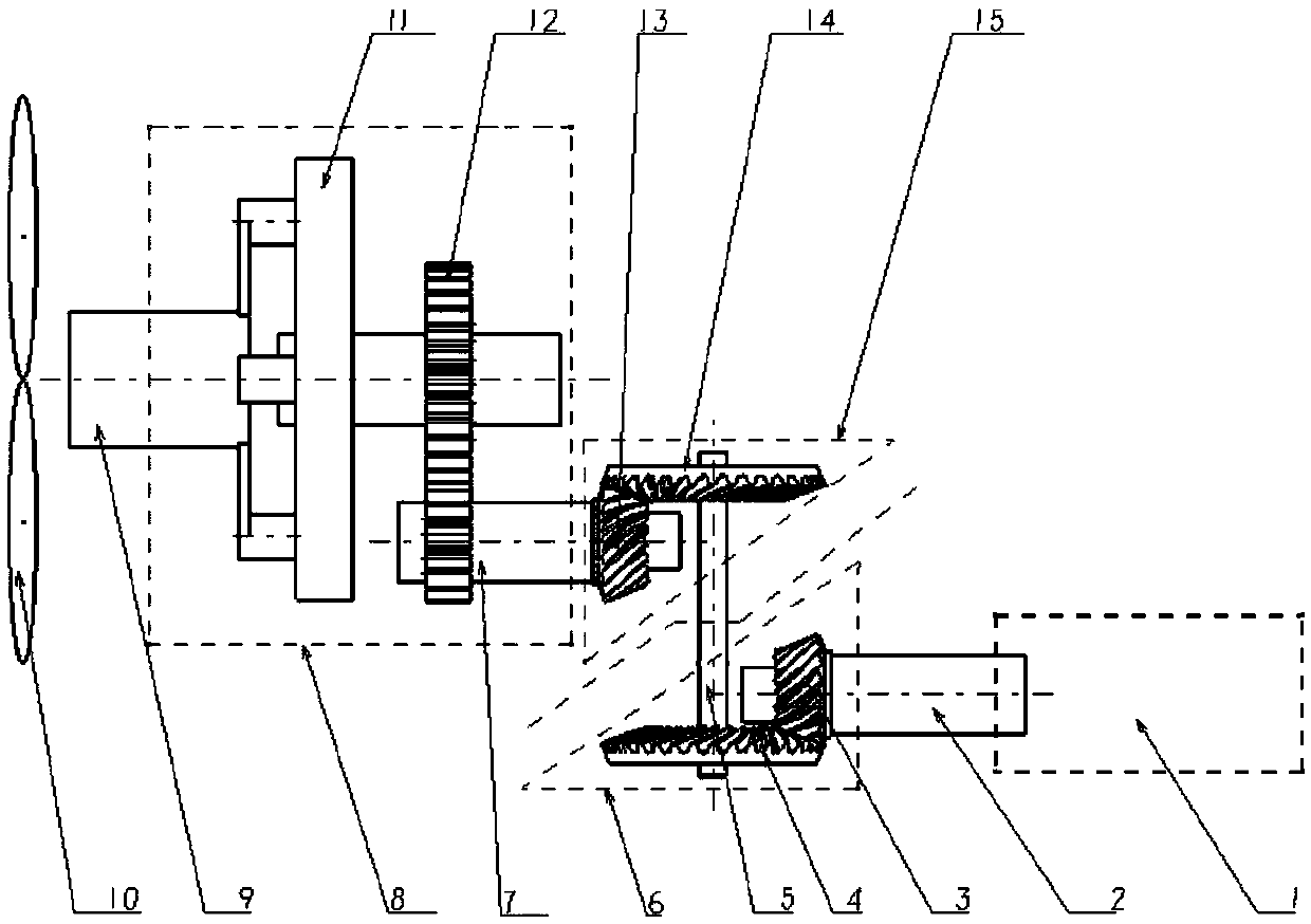
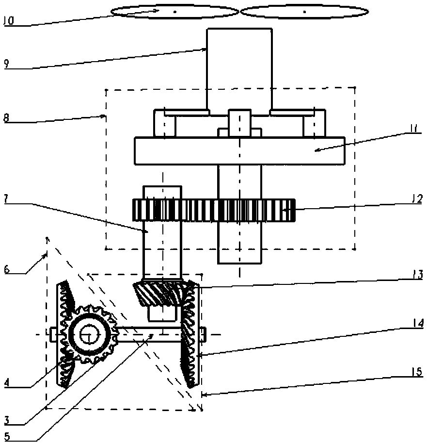
The invention provides a tilting transmission device for fixing an engine, and belongs to the technical field of design of a rotor wing system of a helicopter. The tilting transmission device comprises a fixed end and a tilting end, the fixed end comprises the engine and a second bevel gear meshed with a first bevel gear on the end portion of a first output shaft of the engine, the tilting end comprises a third bevel gear coaxial with the second bevel gear and a fourth bevel gear meshed with the third bevel gear, and a third output shaft connected with the fourth bevel gear drives a propellerto rotate. A control mechanism controls the tilting end to rotate, so that the third output shaft can be converted into a second state from a first state, in the first state, the axis of the third output shaft is parallel to the direction of a longitudinal shaft of the helicopter to achieve forward light, and in the second state, the axis of the third output shaft is parallel to the direction of aperpendicular shaft of the helicopter to achieve lifting. According to the tilting transmission device, tilting of a rotor wing of the propeller is away from the engine so that the engine can be fixed relatively, and difficulty of design and evidence taking of the engine is greatly reduced.

Description

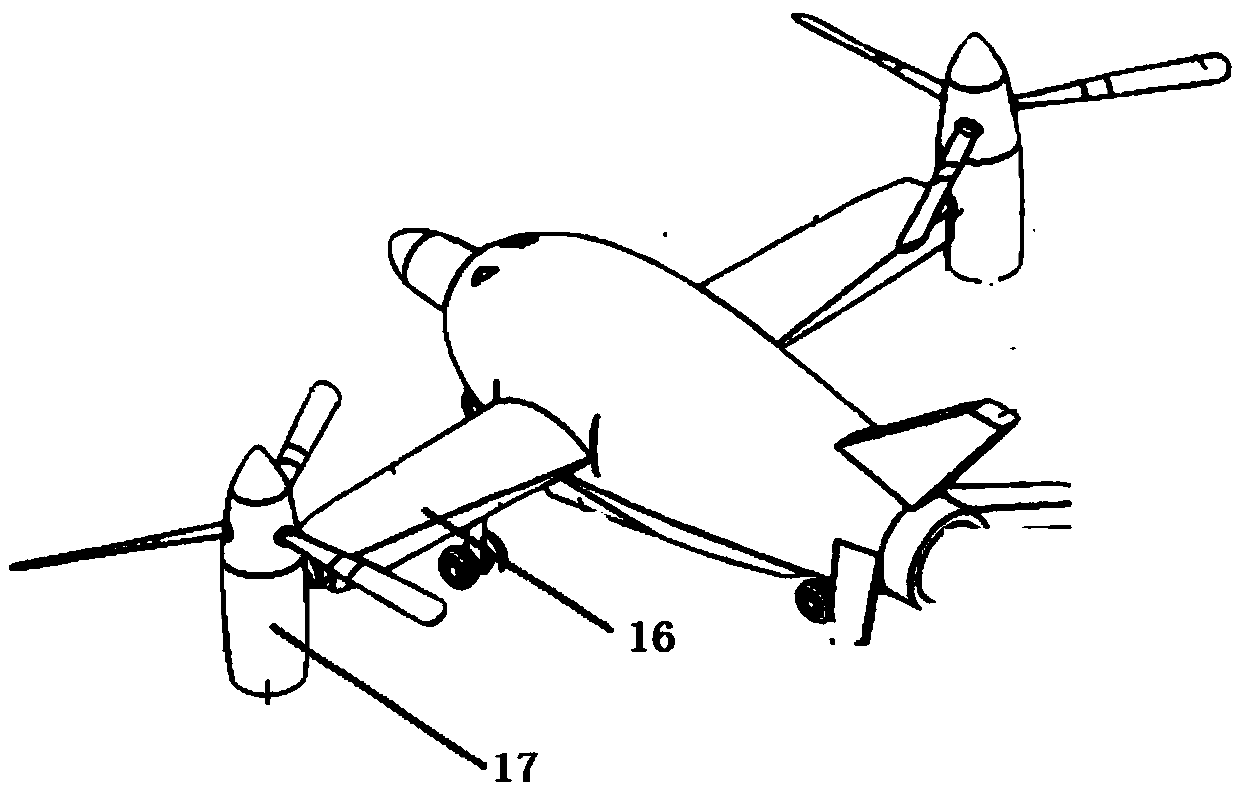
technical field [0001] The invention belongs to the technical field of helicopter rotor system design, in particular to an engine-fixed tilt transmission device. Background technique [0002] The tiltrotor is a unique aircraft, which not only has the vertical take-off and landing and air hovering capabilities of ordinary helicopters, but also can cruise and fly like propeller aircraft. When the plane of rotation of the propeller rotor is parallel to the plane of the fuselage, the aircraft is in helicopter mode and can perform vertical take-off and landing or short-distance take-off and landing; when the plane of rotation of the propeller rotor is perpendicular to the plane of the fuselage, the aircraft becomes In the fixed-wing aircraft mode, the lift of the aircraft is provided by the fixed wings. At this time, the aircraft can fly forward at a high speed. [0003] At present, the tilt rotor mechanism can be divided into two modes: the propeller rotor tilts and the fixed w...

Claims


Application Information

Patent Timeline
IPC IPC(8): B64C27/28B64D27/00B64D35/00
CPCB64C27/28B64D27/00B64D35/00
Inventor 王雷杨萍李英明尤松廖文冬
Owner CHINA HELICOPTER RES & DEV INST
Learn More