Full-automatic saw blade cutting type numerical control processing equipment

A processing equipment and fully automatic technology, applied in metal sawing equipment, metal processing equipment, sawing machine devices, etc., can solve the problems of inability to meet demand, high worker requirements, poor cutting accuracy, etc., to improve sawing accuracy and processing efficiency. , to ensure the cutting efficiency and improve the effect of cutting accuracy

Pending Publication Date: 2019-03-29
苏州艾派克斯数控机械有限公司
View PDF0 Cites 2 Cited by
  • Summary
  • Abstract
  • Description
  • Claims
  • Application Information

AI Technical Summary

Problems solved by technology

The processing of these equipments can only complete the cutting of different angles and different sides by turning the workpiece under manual operation. Poor positioning accuracy leads to poor cutting accuracy. For products with dimensional accuracy requirements within 1mm, special tooling and fixtures must be used to assist in positioning. cutting, it is also difficult to guarantee the cutting accuracy, and the operation is complicated, the requirements for workers are high, and it is difficult to process and produce efficiently in batches
Especially when cutting polygons such as triangles, pentagons, or other combined special-shaped materials and cannot be processed by other methods, only sawing and high angular accuracy are required, and it is difficult to complete products that meet the requirements with manual assistance, and the market has a high demand for product accuracy. The requirements are getting higher and higher, and traditional processing is increasingly unable to meet the demand

Method used


Image

  • Full-automatic saw blade cutting type numerical control processing equipment
  • Full-automatic saw blade cutting type numerical control processing equipment
  • Full-automatic saw blade cutting type numerical control processing equipment

Examples


Embodiment Construction

[0019] The following examples are used to illustrate the present invention, but are not intended to limit the scope of the present invention.

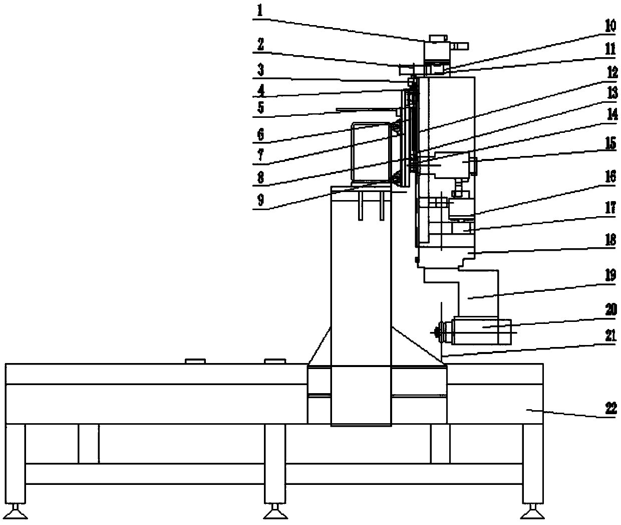
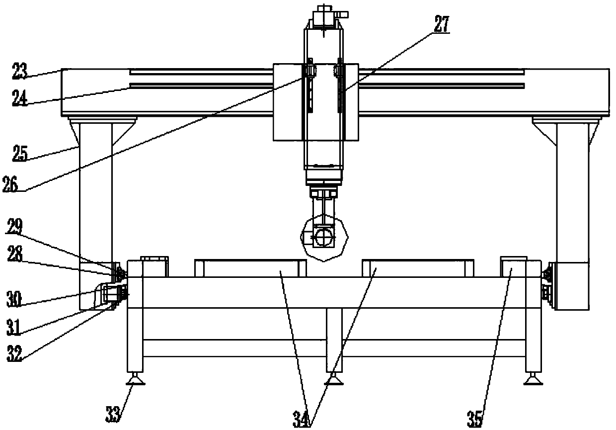
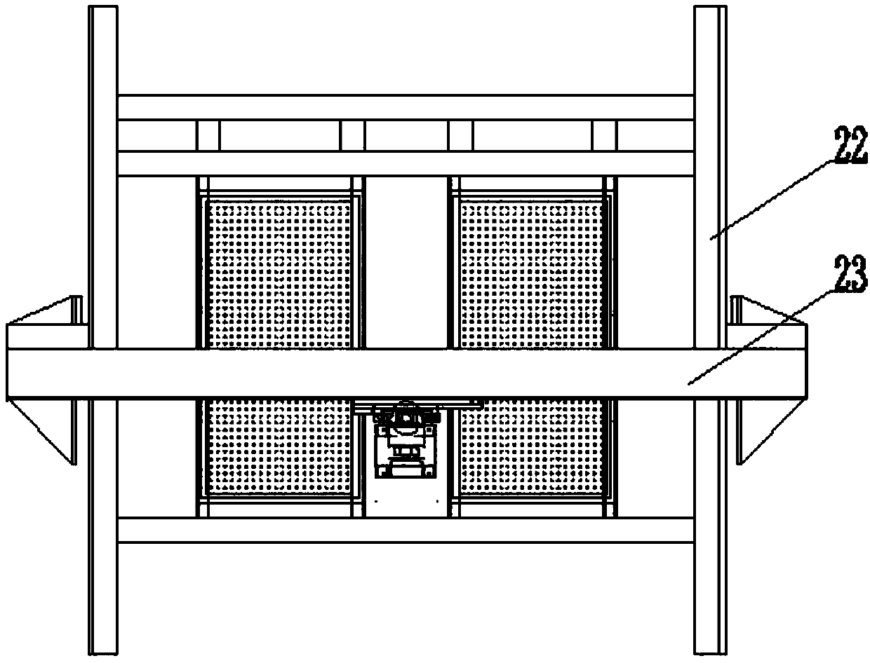
[0020] The present invention will be described in detail below in conjunction with the accompanying drawings and specific embodiments, as shown in the figure: a fully automatic saw blade cutting numerical control processing equipment, including a bed 22, a beam 23 arranged above the bed 22, and a beam 23 installed on the The main shaft 20 on the top and the blade 21 arranged at the end of the main shaft 20, the two sides of the bed body 22 are symmetrically provided with side columns 25, and the two ends of the crossbeam 23 are respectively fixedly connected with the side column 25, and the crossbeam 23 The X-axis servo motor 15 that drives the main shaft 20 to move along the X-axis direction is installed on the top, and the Y-axis servo motor 31 that drives the side column 25 to move along the Y-axis direction is installed on the side ...


PUM


Abstract

The invention discloses full-automatic saw blade cutting type numerical control processing equipment. The full-automatic saw blade cutting type numerical control processing equipment comprises a lathebody, a transverse beam arranged above the lathe body, a main shaft mounted on the transverse beam and a saw blade arranged at the end part of the main shaft, wherein lateral stand columns are symmetrically arranged at two sides of the lathe body; two ends of the transverse beam are fixedly connected with the lateral stand columns; the transverse beam is provided with an X-axis servo motor for driving the main shaft to move along the X-axis direction; each lateral stand column is provided with a Y-axis servo motor for driving the lateral stand column to move along the Y-axis direction; the transverse beam is provided with a Z-axis servo motor for driving the main shaft to move along the Z-axis direction; the transverse beam is provided with a C-axis servo motor for driving the main shaftto rotate along the C-axis direction; the X-axis direction, the Y-axis direction and the Z-axis direction are mutually vertical; the C-axis direction is parallel to the upper surface of the lathe body; and the Z-axis direction is vertical to the C-axis direction. The full-automatic saw blade cutting type numerical control processing equipment disclosed by the invention can be used for carrying out360-degree cutting at any angle; and the cutting efficiency is ensured and the cutting precision also can be greatly improved.

Description

technical field [0001] The invention relates to the field of sawing processing equipment, in particular to a fully automatic saw blade cutting numerical control processing equipment. Background technique [0002] At present, known equipment that adopts saw blades for cutting includes sliding table saws, electronic sizing saws, table saws, and similar equipment. The processing of these equipments can only complete the cutting of different angles and different sides by turning the workpiece under manual operation. Poor positioning accuracy leads to poor cutting accuracy. For products with dimensional accuracy requirements within 1mm, special tooling and fixtures must be used to assist in positioning. Cutting, it is also difficult to ensure the cutting accuracy, and the operation is complicated, which requires high workers, and it is difficult to process and produce efficiently in batches. Especially when cutting polygons such as triangles, pentagons, or other combined special...

Claims


Application Information

Patent Timeline
Patent Type & Authority Applications(China)
IPC IPC(8): B23D45/18
CPCB23D45/18
Inventor 万思宾
Owner 苏州艾派克斯数控机械有限公司
Why Eureka
Try Eureka