Closing-in type mud centrifugal equipment

A kind of centrifugal equipment, closed-mouth technology, applied in centrifuges, centrifuges with rotating drums, etc., can solve the problems of damage, reduce the diameter of the outer cylinder, large size, etc., save volume space, avoid accumulation and solidification, use long life effect

Active Publication Date: 2019-03-29
CHANGSHA UNIVERSITY OF SCIENCE AND TECHNOLOGY
View PDF6 Cites 0 Cited by
  • Summary
  • Abstract
  • Description
  • Claims
  • Application Information

AI Technical Summary

Problems solved by technology

[0004] 1. The outer cylinder of the centrifuge in the prior art needs to be larger in size, because the outer cylinder contains relatively solid mud and needs to be discharged, and there is a waste of space, but the diameter of the outer cylinder cannot be reduced because of the reduction. It is not enough to accommodate a large number of mud parts, so it causes troubles. The solution is often to directly use a large-diameter outer cylinder, but it does not meet the design trend of miniaturization and refinement
[0005] 2. The centrifuge in the prior art lacks maintenance means, and only part of it can be cleaned during cleaning, and there is a cleaning dead angle
[0006] 3. A part of the centrifuge in the prior art is provided with a drain pipe or a liquid collecting pipe, which is often exposed in the drum and is washed by centrifugal particles. When there are stones in the mud, it is easy to rotate and damage the drain pipe; for this reason The solution is often to increase the material hardness of the discharge pipe, but it increases the cost
[0007] 4. There is a discharge valve under the centrifuge in the prior art, but the discharge valve is directly impacted by the centrifuged material, and it is easy to loosen or even be damaged after a long time
[0008] 5. After the centrifuge in the prior art is used for a long time, it will accumulate materials that are difficult to remove, even if it is impacted by water, it cannot be removed

Method used


Image

  • Closing-in type mud centrifugal equipment
  • Closing-in type mud centrifugal equipment
  • Closing-in type mud centrifugal equipment

Examples


Embodiment Construction

[0033] The present invention will be further described below in conjunction with the accompanying drawings and embodiments.

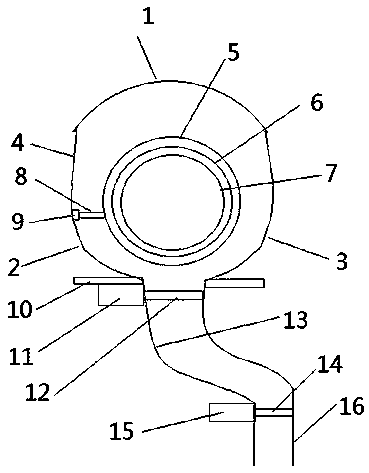
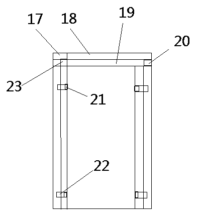
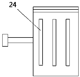
[0034] As shown in the figure: a closing type mud centrifugal equipment, including the first arc, the second arc, the third arc, the connecting section, the outer wall, the middle wall, the inner wall, the scraper rod, the scraper, the bracket, the first cylinder, the first gate Plate, mud-bearing arc wall, second ram, second cylinder, main body wall, multi-function tank, outer maintenance plate, inner maintenance plate, drain purge port, top wall of drain pipe, drain pipe, auxiliary blower Sweep port, mud discharge grill; the mud centrifugal equipment includes a centrifuge and a discharge valve, both of which are fixed on the bracket, the centrifuge includes an inner cylinder and an outer cylinder, and the outer cylinder includes a first arc , the second arc, the third arc, the connecting segment, the two ends of the first arc connect the second arc an...


PUM


Abstract

The invention discloses closing-in type mud centrifugal equipment. The closing-in type mud centrifugal equipment comprises a centrifugal machine and a discharging valve; the centrifugal machine and the discharging valve are fixed to a support, the centrifugal machine comprises an inner cylinder and an outer cylinder, the outer cylinder comprises a first arc, a second arc, a third arc, and a connecting segment, the two ends of the first arc are connected with the second arc and the third arc through the connecting segment, the radius of the first arc is larger than that of the second arc, the radius of the first arc is larger than that of the third arc, the second arc and the third arc are the same in radius, a closing-in part is formed downwards, the diameter of the closing-in part is equal to that of a support opening, and the connecting segment is not bent; a scraping knife segment and a scraping knife are arranged between the inner cylinder and the outer cylinder, the scraping kniferod is connected to the inner cylinder, and the sum of the length of the scraping knife rod and the length of the scraping knife is equal to the distance between the second arc and the third arc andthe inner cylinder, and smaller than the distance between the connecting segment and the first arc and the inner cylinder.

Description

technical field [0001] The invention relates to the related field of mud treatment, in particular to a closing type mud centrifugal equipment. Background technique [0002] With the development of science and technology and economic development, the amount of mud used is increasing. At present, the mud in the city mainly comes from construction engineering mud, municipal sludge and river silt. With the continuous acceleration of urbanization, high-rise, super There are more and more constructions of various projects such as high-rise buildings, subways, expressways, and large bridges, and the amount of mud produced is also increasing. At present, there are mainly the following ways to deal with mud: 1) Tanker truck (mud truck) for external transportation. This method is to directly lift the mud generated on site into the mud truck through the mud pump, and transport the mud to the outskirts of the city through the mud truck. 2) On-site sedimentation and drying, this method ...

Claims


Application Information

Patent Timeline
Patent Type & Authority Applications(China)
IPC IPC(8): B04B1/06B04B5/00B04B7/08B04B7/18B04B15/06B04B11/04
CPCB04B1/06B04B5/00B04B7/08B04B7/18B04B11/04B04B15/06
Inventor 尹来容易继军陈敏慧黄龙杜荣华
Owner CHANGSHA UNIVERSITY OF SCIENCE AND TECHNOLOGY
Why Eureka
Try Eureka