Double-screw extruder for producing powder coating

A twin-screw extruder and powder coating technology, applied in the field of twin-screw extruders, can solve problems such as the reduction of raw material conveying efficiency

Active Publication Date: 2014-11-12
华威控股集团温州福鑫电气有限公司
View PDF5 Cites 0 Cited by
  • Summary
  • Abstract
  • Description
  • Claims
  • Application Information

AI Technical Summary

Problems solved by technology

[0002] The raw materials required for powder production include resins, curing agents, additives, and pigments. The processing temperature of materials such as resins, curing agents, and additives in the production process should be 5°C higher than the softening point to melt the materials to achieve the effect of mixing and shearing. In the prior art, powder coatings usually use a twin-screw extruder to melt and extrude the powder during the production process. Due to the need to heat the screw barrel to the softening temperature of the raw material, and the interaction between the two internal screws A lot of heat is generated, so the temperature on the screw will be much higher than the softening temperature. When the temperature reaches a certain level, it will reach the glass transition temperature of the resin. When the temperature is higher than the glass transition temperature of the resin, the resin will appear. Its viscous characteristics, at this time, the raw material will be attached to the screw, so that the screw cannot drive the raw material out of the extruder, so that the material stays in the screw barrel for a long time to gel or solidify, so that the dead angle of the two screws will become There is solidification and accumulation of raw materials, which reduces the efficiency of the two screws for raw material transportation

Method used


Image

  • Double-screw extruder for producing powder coating
  • Double-screw extruder for producing powder coating
  • Double-screw extruder for producing powder coating

Examples


Embodiment Construction

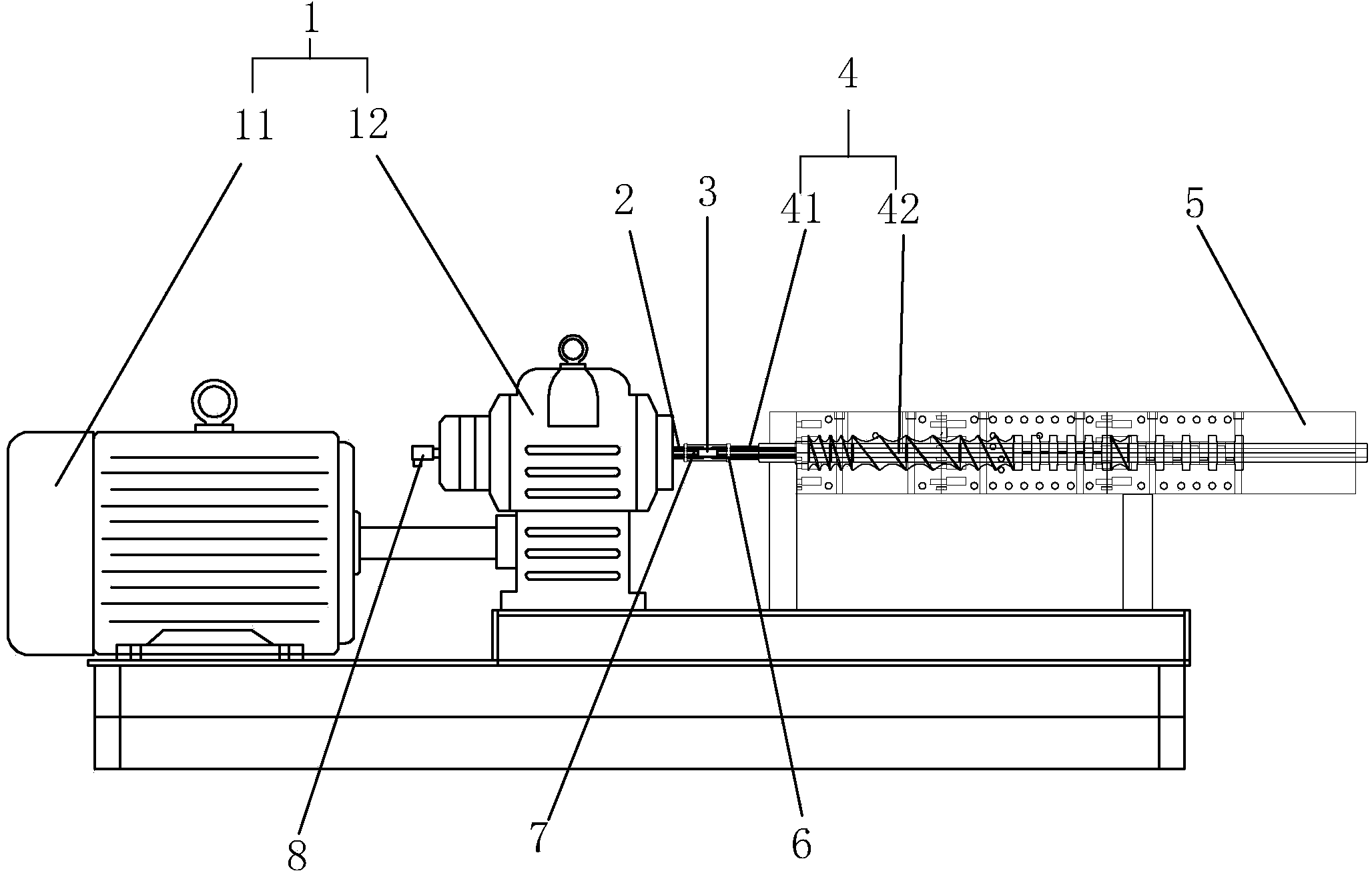
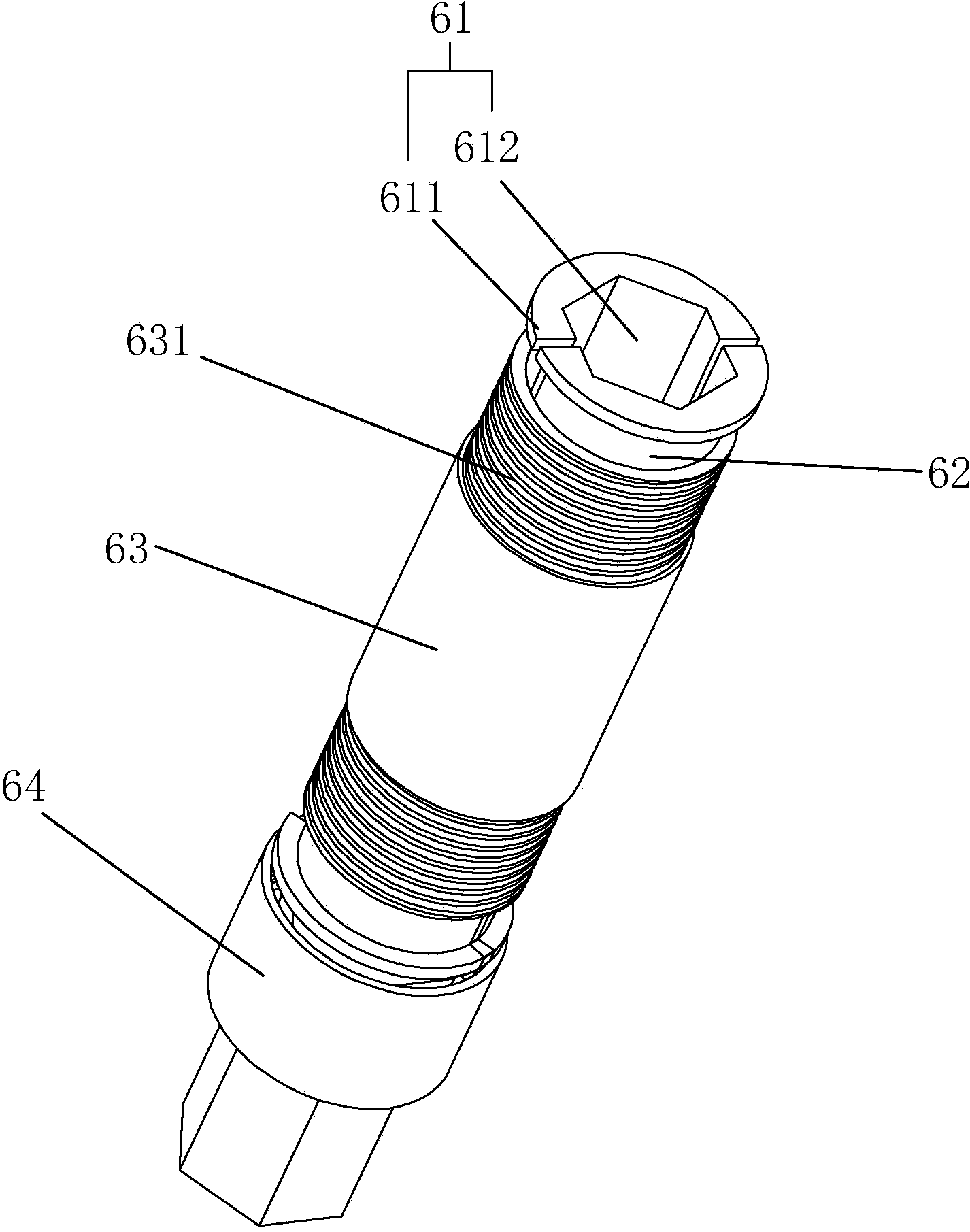
[0021] refer to Figure 1 to Figure 5 The embodiment of the twin-screw extruder used in the production of powder coatings according to the present invention will be further described.

[0022] A twin-screw extruder for producing powder coatings, comprising a screw barrel 5, two cooperating screw rods 4 arranged in the screw barrel 5, and a power mechanism 1 for driving the two screw rods 4 to rotate, and the screw rod 4 includes There is a transmission part 42 arranged inside the screw barrel 5 and a transmission shaft 41 located outside the screw barrel 5, the power mechanism 1 includes a drive shaft 2 and a water channel 24 is arranged inside the drive shaft 2, and the water channel 24 includes There is a water inlet 21 and a water outlet 23. The drive shaft 2 is connected to the drive shaft 41 on the side of the water outlet 23 through a connecting assembly. The screw 4 is provided with a cooling tank 43 for water circulation. The cooling tank 43 and the water channel 24 c...


PUM


Abstract

The invention discloses a double-screw extruder for producing a powder coating. The double-screw extruder comprises a screw drum, two screws and a power mechanism, wherein each screw rod comprises a transmission part and a transmission shaft; the power mechanism comprises a driving shaft in which a water tank is arranged; the water tank comprises a water inlet end and a water outlet end; a connecting assembly is arranged between one side of the driving shaft, which is located at the water outlet end, and the transmission shaft; a cooling tank is arranged inside each screw rod; the cooling tanks are communicated with the water tank; the water tank is internally provided with a water inlet pipe; a gap is formed among the water inlet pipe, the cooling tanks and the water tank; the water inlet pipe is externally connected with a water supply source; the other side of the driving shaft, which is located at the water inlet end, is provided with a water outlet; and the water outlet is communicated with a gap formed between the driving shaft and the water inlet pipe. By using the double-screw extruder for producing the powder coating, disclosed by the invention, materials can be smoothly extruded from the screws, raw materials can be prevented from being accumulated and cured at dead angles of the two screws, and the two screws can be used for conveying raw materials at high efficiency for a long term.

Description

technical field [0001] The present invention relates to a twin-screw extruder, more particularly, it relates to a twin-screw extruder for producing powder coatings. Background technique [0002] The raw materials required for powder production include resins, curing agents, additives, and pigments. The processing temperature of materials such as resins, curing agents, and additives in the production process should be 5°C higher than the softening point to melt the materials to achieve the effect of mixing and shearing. In the prior art, powder coatings usually use a twin-screw extruder to melt and extrude the powder during the production process. Due to the need to heat the screw barrel to the softening temperature of the raw material, and the interaction between the two internal screws A lot of heat is generated, so the temperature on the screw will be much higher than the softening temperature. When the temperature reaches a certain level, it will reach the glass transitio...

Claims


Application Information

Patent Timeline
Patent Type & Authority Applications(China)
IPC IPC(8): B29C47/40B29C47/58B29C48/50
CPCB29C48/03B29C48/402B29C48/82B29C48/85
Inventor 陈玉才
Owner 华威控股集团温州福鑫电气有限公司
Why Eureka
Try Eureka