
Method for forming embedded flash memory structure

An embedded, flash memory technology, applied in electrical components, electrical solid-state devices, circuits, etc., can solve the problems of many etching steps to remove the deposition layer, complex processes, and increased process costs.

Active Publication Date: 2019-03-26
SHANGHAI HUAHONG GRACE SEMICON MFG CORP
View PDF2 Cites 1 Cited by
  • Summary
  • Abstract
  • Description
  • Claims
  • Application Information

AI Technical Summary

Problems solved by technology

[0004] The purpose of the present invention is to provide a method for forming an embedded flash memory structure, so as to solve the problem in the prior art that there are many etching steps for removing the deposition layer in the logic area, the process is complicated, and the process cost increases.

Method used


Image

  • Method for forming embedded flash memory structure
  • Method for forming embedded flash memory structure
  • Method for forming embedded flash memory structure

Examples


Embodiment Construction

[0038] The specific implementation manner of the present invention will be described in more detail below with reference to schematic diagrams. The advantages and features of the present invention will be more apparent from the following description. It should be noted that all the drawings are in a very simplified form and use imprecise scales, and are only used to facilitate and clearly assist the purpose of illustrating the embodiments of the present invention.

[0039] In the following description, it will be understood that when a layer (or film), region, pattern or structure is referred to as being "on" a substrate, layer (or film), region and / or pattern, it can be directly on another layer or substrate, and / or intervening layers may also be present. Further, it will be understood that when a layer is referred to as being 'under' another layer, it can be directly under, and / or one or more intervening layers may also be present. In addition, designations regarding 'on' ...


PUM


Abstract

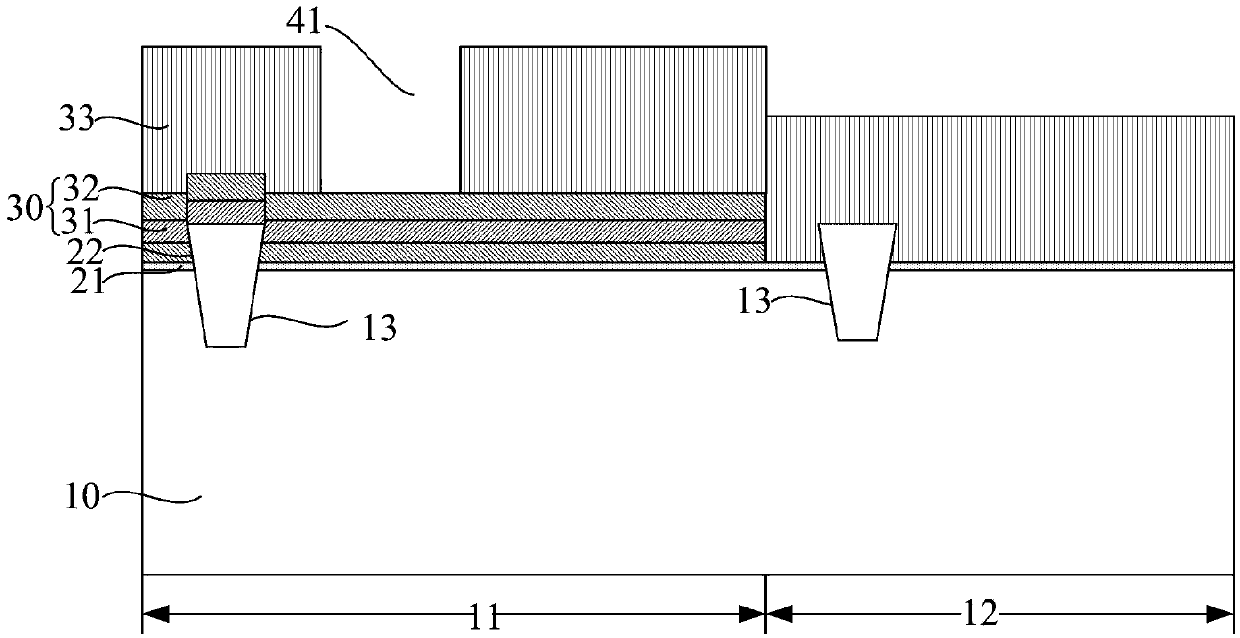
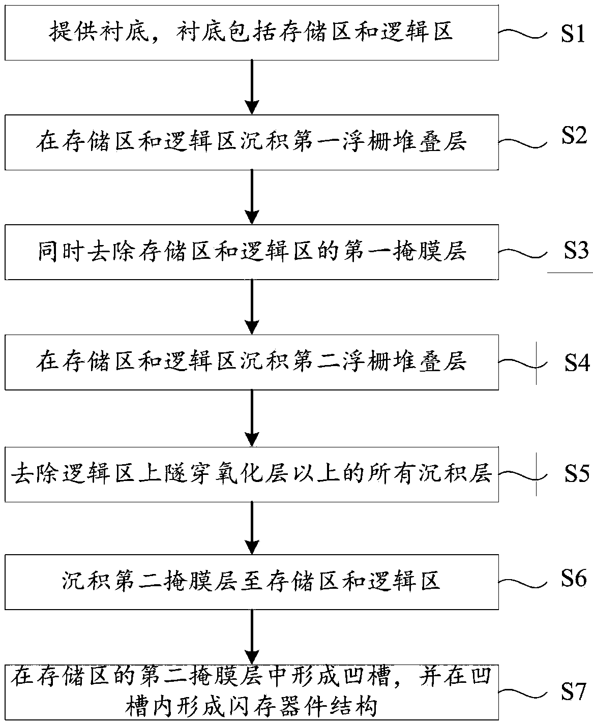
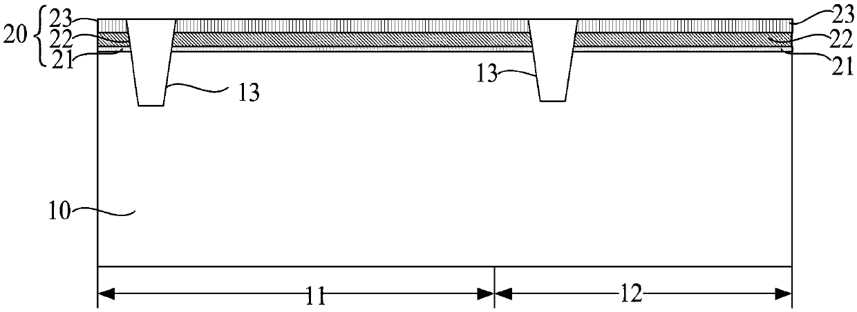
The invention relates to a method for forming an embedded flash memory structure. The method comprises a steps of providing a substrate comprising a memory area and a logic area, a step of depositinga first floating gate stack layer in the memory area and the logic area, wherein the first floating gate stack layer includes a tunneling oxide layer, a first floating gate layer and a first mask layer deposited in sequence, a step of simultaneously removing the first mask layer of the memory region and the logic region, a step of depositing a second floating gate stack layer on the memory regionand the logic region, a step of removing all deposited layers above the tunneling oxide layer on the logic region, a step of depositing a second mask layer to the memory region and the logic region, astep of forming a recess in the second mask layer of the memory region to form a flash memory device structure in the groove. In the invention, the second mask layer of the memory region and the logic region is simultaneously removed by using one wet etching, and a lithography step used in removing all deposited layers of the logic region is reduced. The process steps of the method for forming the embedded flash memory structure are reduced, and the cost is saved.

Description

technical field [0001] The invention relates to the field of semiconductors, in particular to a method for forming an embedded flash memory structure. Background technique [0002] In recent years, with the rapid development of the smart electronic product market, the use of various MCU (micro controller unit, microcontroller) and SoC (System-on-Chip, system-on-chip) chips has penetrated into automotive electronics, industrial control and medical Products and other aspects of daily life. And high-performance MCU or SoC products are inseparable from the support of high-performance embedded flash memory (embedded flash, E-flash) core. No matter in terms of chip area, system performance and power consumption, or in terms of manufacturing yield and design cycle, the leading role of embedded flash memory in SoC design is increasing. Embedded flash memory is a physical or electrical combination of existing flash memory and logic modules to provide more diverse performance. [0...

Claims


Application Information

Patent Timeline
Patent Type & Authority Applications(China)
IPC IPC(8): H01L27/11521H01L27/11531H10B41/30H10B41/42
CPCH10B41/42H10B41/30
Inventor 江红王哲献
Owner SHANGHAI HUAHONG GRACE SEMICON MFG CORP
Learn More