
Device for realizing two-side temperature field environment test of test element

An environmental test device and test piece technology, applied in the direction of measurement device, strength characteristics, instruments, etc., can solve the problems of slow heat conduction of plexiglass, affecting the mechanical properties of the transparent parts of the cockpit cover, and the lack of finished products in the high and low temperature comprehensive environmental test system. Satisfy the effect of strength, moderate weight and low cost

Inactive Publication Date: 2019-03-26
XIAN AIRCRAFT DESIGN INST OF AVIATION IND OF CHINA
View PDF9 Cites 1 Cited by
  • Summary
  • Abstract
  • Description
  • Claims
  • Application Information

AI Technical Summary

Problems solved by technology

The data show that the temperature of the outer layer of the transparent part of the canopy changes within the range of -55 to 100 °C, while the temperature of the inner layer is basically maintained at around room temperature. In addition, the heat conduction of plexiglass is slow, so there is a temperature gradient between the inner and outer sides of the transparent part of the canopy. The temperature difference environment will inevitably affect the mechanical properties of the transparent part of the canopy
However, due to the limitation of test conditions, especially the simulation of environmental conditions, so far, there have been no reports in this regard. There is currently no finished product for the high and low temperature comprehensive environmental test system based on the material testing machine that meets the test requirements. Even at present, there are no national standards and industry standards for such environmental devices. Therefore, it is necessary to develop an environmental test device that realizes the temperature field on both sides of the test piece to determine the strength and fatigue life of aircraft materials when there is a temperature gradient on the inner and outer sides. very necessary

Method used


Image

  • Device for realizing two-side temperature field environment test of test element
  • Device for realizing two-side temperature field environment test of test element
  • Device for realizing two-side temperature field environment test of test element

Examples


Embodiment Construction

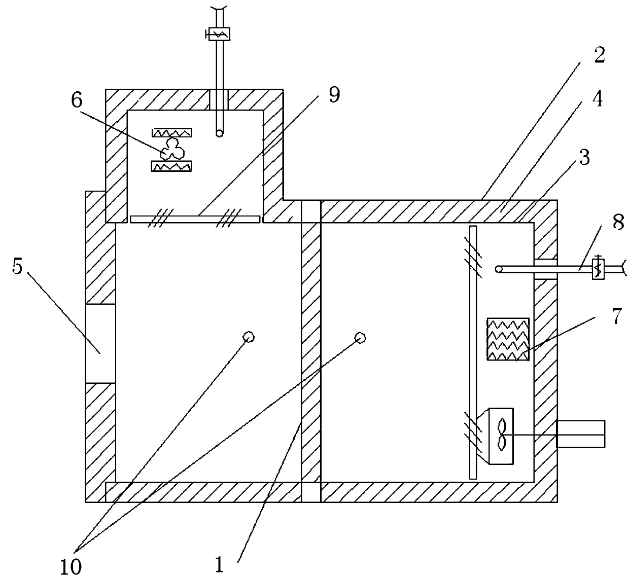
[0011] See attached Figure 1-3 , an environmental test device for realizing the temperature field on both sides of the test piece, which consists of two parts: a box body and a control system; the box body is a butt joint split structure, consisting of an outer shell (2), an inner tank (3), and a heat insulating layer (4) , to ensure a constant temperature in the box; the whole box is divided into two independent areas by the middle partition (1), and the middle partition (1) is shaped according to the shape of the sample and the fixture by the heat insulating material with good plasticity; the control system It consists of a fan system (6), a heating facility (7), a cooling facility (8), an air deflector (9), and a temperature sensor (10), and is used to control the temperature environment of two independent areas in the cabinet.

[0012] On the basis of the above device, the shell (2) is made of thin steel plate and painted; the inner tank (3) is made of stainless steel pla...


PUM


Abstract

The invention belongs to a structure intensity test technology, and particularly relates to a device for realizing the two-side temperature field environment test of a test element. The device consists of two parts including a box body part and a control system, wherein the box body part is of a butt joint type split structure, and is separated into two regions by a middle separation plate; the split structure is convenient for test sample installation; the middle separation plate is shaped by a heat insulation material with good plasticity according to the shape of a test sample and a clamp,and can leftwards and rightwards move in the box body; the box body consists of a case, an inner liner, a heat insulation layer and an observation window; the case is a high-quality thin steel plate and is subjected to paint spraying treatment; the inner liner is a stainless steel plate; a high-quality cotton heat insulation material is filled in the heat insulation layer; the heat conduction is well prevented; the heat insulation effect is also achieved. The control system comprises a fan system, a heat facility, a refrigeration facility, an air guide plate and a temperature sensor. The environment test device has the advantages that the materials can be easily bought; the cost is low; the process is simple; the processing is easy; the test element can be easily installed or dismounted; the intensity is met; safety and reliability are realized; the universality is high.

Description

technical field [0001] The invention belongs to the structural strength test technology, and relates to an environmental test device for realizing the temperature field on both sides of a test piece. Background technique [0002] Aircraft canopy is an exposed part. The temperature of the outer layer changes due to changes in flight speed, altitude, flight status and atmospheric temperature environment, while the inner layer does not change much due to the air-conditioning system inside the cockpit. The data show that the temperature of the outer layer of the transparent part of the canopy changes within the range of -55 to 100 °C, while the temperature of the inner layer is basically maintained at around room temperature. In addition, the heat conduction of plexiglass is slow, so there is a temperature gradient between the inner and outer sides of the transparent part of the canopy. The temperature difference environment will inevitably affect the mechanical properties of th...

Claims


Application Information

Patent Timeline
Patent Type & Authority Applications(China)
IPC IPC(8): G01N3/60
CPCG01N3/60G01N2203/0057G01N2203/0064G01N2203/0066G01N2203/0075
Inventor 惠战荣杨沛候店林
Owner XIAN AIRCRAFT DESIGN INST OF AVIATION IND OF CHINA
Learn More