
Method for determining spatial coordinates of rotation center of turntable

A determination method and a technology of spatial coordinates, applied in the field of determining the spatial coordinates of the rotary center of the turntable, to achieve the effect of great implementability and application value

Active Publication Date: 2019-03-26
CHINA PRECISION ENG INST FOR AIRCRAFT IND AVIC
View PDF4 Cites 11 Cited by
  • Summary
  • Abstract
  • Description
  • Claims
  • Application Information

AI Technical Summary

Problems solved by technology

At present, there is no effective and reliable solution to the problem of determining the spatial coordinates of the turntable center of rotation in a four-axis visual coordinate measurement system.

Method used


Image

  • Method for determining spatial coordinates of rotation center of turntable
  • Method for determining spatial coordinates of rotation center of turntable
  • Method for determining spatial coordinates of rotation center of turntable

Examples


Embodiment Construction

[0040] The technical scheme of the present invention will be described in further detail below in conjunction with accompanying drawing and embodiment:

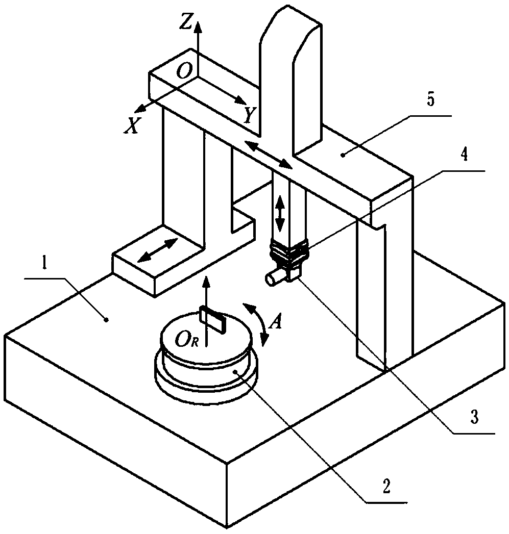
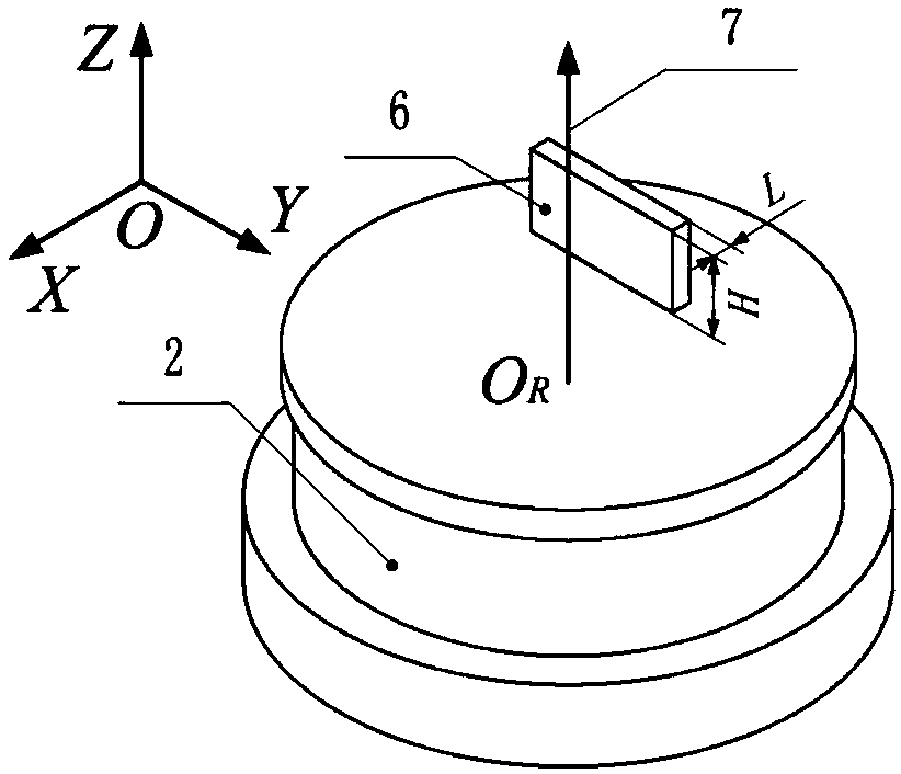
[0041] See attached figure 1 As shown, the visual coordinate measurement system includes a workbench 1 , a turntable 2 , an imaging device 3 , an attitude adjustment mechanism 4 and a three-dimensional moving bridge 5 . The machine coordinate system O-XYZ of the visual coordinate measurement system is a space rectangular coordinate system, and the directions of its X, Y and Z coordinate axes are respectively the same as the directions of the three linear motion axes of the system, while the origin O is located on each linear motion axis through mechanical adjustment, make the rotation axis 7 of the turntable 2 parallel to the Z-axis direction of the visual coordinate measurement system, that is, its unit direction vector in O-XYZ is (0,0,1).

[0042] The workbench 1 and the three-dimensional mobile bridge frame 5 are realize...


PUM


Abstract

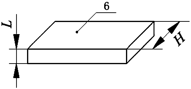
The invention provides a method for determining the spatial coordinates of the rotation center of a turntable. The method is based on a visual coordinate measuring system which is composed of a worktable, a turntable, an imaging device, an attitude adjustment mechanism and a three-dimensional moving bridge and has three linear motion axes X, Y, Z and a rotary motion axis A. By means of a cuboid calibration block made of hard alloy steel, the method accomplishes image acquisition for edges of the calibration block at different angular positions through the spatial linear motion of the three-dimensional moving bridge and the rotary motion of the turntable, the grating scale reading of each linear motion axis is recorded at the same time, and finally the three-dimensional spatial coordinatesof the rotation center of the turntable in a machine coordinate system of the multi-axis visual coordinate measuring system are solved by combining the thickness and height of the calibration block according to an image processing technology. The method is simple in principle and convenient in application, solves key problems in multi-axis visual coordinate measurement of rotary parts, and has great practicability and practical application values.

Description

technical field [0001] The invention relates to a method for determining the spatial coordinates of the center of rotation of a turntable, which belongs to the technical field of measurement and testing. Background technique [0002] In many industrial fields such as aviation, aerospace, weapons and ships, rotary parts account for a large proportion of various parts. Generally speaking, revolving parts refer to mechanical parts whose shape characteristics conform to the characteristics of revolving bodies. Although the structure and size of revolving parts are different due to their different uses, the detection and control of their structure and size parameters have great significance. High requirements, because many rotary parts are key components of mechanical equipment, their shape and position errors and manufacturing accuracy will have a great impact on their assembly and use performance, not only will affect the matching properties of the contact surface , It will al...

Claims


Application Information

Patent Timeline
Patent Type & Authority Applications(China)
IPC IPC(8): G01B11/00
CPCG01B11/00G01B11/005
Inventor 毕超刘孟晨郝雪韩海涛房建国
Owner CHINA PRECISION ENG INST FOR AIRCRAFT IND AVIC
Learn More