Coiled tubing well-drilling robot control system capable of controlling drilling speed and bit pressure
A technology for controlling the drilling speed and drilling speed, which is applied to the automatic control system of drilling, drilling equipment, earthwork drilling and production, etc., and can solve the problems that the drilling speed and drilling pressure cannot be controlled.
- Summary
- Abstract
- Description
- Claims
- Application Information
AI Technical Summary
Problems solved by technology
Method used
Image
Examples
Embodiment 1
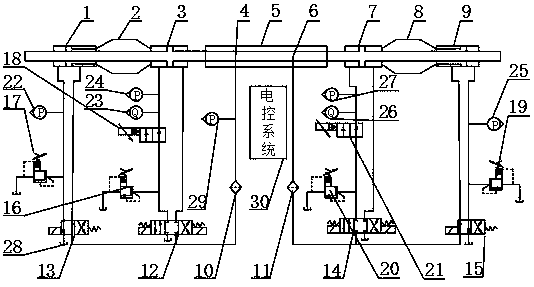
[0031] Embodiment 1: as figure 2As shown, the drilling robot 34 is composed of a left working joint, a right working joint and a control joint 5, wherein the left working joint is composed of a left supporting cylinder 1, a left supporting arm 2 and a left telescopic cylinder 3, and the right working joint is composed of The right telescopic cylinder 6, the right support arm 7 and the right support cylinder 9 are composed; the control system introduces the drilling fluid in the drilling robot 34 through the left liquid inlet 4 into the left support cylinder 1 and the left telescopic cylinder 3, and through the right liquid inlet 5 Introduce it into the right support cylinder 9 and right telescopic cylinder 7; the drilling fluid in the support telescopic cylinder is directly discharged to the bottom annulus 28; left filter 10, right filter 11, three-position four-way electromagnetic reversing valve A12, two-position Four-way electromagnetic directional valve A13, three-positio...
Embodiment 2
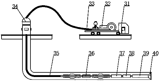
[0034] Embodiment 2: as Figure 1-2 As shown, a system for controlling drilling speed and WOB of coiled tubing drilling includes coiled tubing intelligent drilling rig 31, wellhead device 32, coiled tubing 33, drilling robot 34, drill string vibration measuring device 35, MWD36, power drilling tool 37 , drill bit 38, coiled tubing intelligent drilling rig 31 sends coiled tubing 33 to the bottom of the well through wellhead device 32, and the front end of coiled tubing is connected to drilling robot 34, drill string vibration measuring device 35, MWD36, power drilling tool 37 and drill bit 38 in sequence. The coiled tubing intelligent drilling rig 31 is equipped with a mud pump, a mud pulse signal generator and a ground control system. The drilling robot uses mud as a power source, and the ground control system can control the start and stop of the robot through the mud pulse signal generator.
[0035] The drilling robot 34 is equipped with an electric proportional overflow val...
Embodiment 3
[0037] Embodiment 3: as Figure 1-2 As shown, the method for controlling the drilling speed and the weight-on-bit of coiled tubing drilling comprises the following steps:
[0038] S1. The coiled tubing intelligent drilling rig 35 sends out mud pressure pulse waves to start the drilling robot 34;
[0039] S2, the drilling robot 34 pushes the drill string to drill forward;
[0040] S3. When the drill string is drilling forward, the drill string vibration measurement device 35 measures the drill string vibration in real time;
[0041] S4. The drilling robot 34 pushes the drill string to drill forward with the optimal drilling speed and WOB according to the drill string vibration measured by the drill string vibration measuring device 35;
[0042] S5. The drilling robot 34 stops drilling.
[0043] The step S2 specifically includes the following steps:
[0044] S21: The drilling robot 34 judges a series of factors that affect drilling, such as the depth of the formation where t...
PUM
 Abstract
Description
Claims
Application Information
 - R&D
- Intellectual Property
- Life Sciences
- Materials
- Tech Scout
- Unparalleled Data Quality
- Higher Quality Content
- 60% Fewer Hallucinations
Browse by: Latest US Patents, China's latest patents, Technical Efficacy Thesaurus, Application Domain, Technology Topic, Popular Technical Reports.
© 2025 PatSnap. All rights reserved.Legal|Privacy policy|Modern Slavery Act Transparency Statement|Sitemap|About US| Contact US: help@patsnap.com


