
Cross-scale part automatic assembling device and method of weak rigidity framework type structure

An automatic assembly device and frame-type technology, applied in metal processing, metal processing equipment, manufacturing tools, etc., can solve the problems of no alignment positioning, low degree of automation, and inability to adjust alignment

Active Publication Date: 2019-03-26
DALIAN UNIV OF TECH
View PDF12 Cites 4 Cited by
  • Summary
  • Abstract
  • Description
  • Claims
  • Application Information

AI Technical Summary

Problems solved by technology

Aiming at the threading and centering process of the suspension wire, the invention patent No. 201110178911.X, Huang Wenbin invented a device for threading the platinum wire in the quartz tube. The device uses the roller to guide the platinum wire. The surface causes certain damage, and there is no centering positioning; Invention Patent No. 201410855198.1, Li Juan and others invented a microchannel threading device that can achieve alignment and threading. Correct, after the wire threading is completed, the centering cannot be carried out
[0004] In summary, it can be seen that the existing assembly methods are more dependent on workers and have a lower degree of automation

Method used


Image

  • Cross-scale part automatic assembling device and method of weak rigidity framework type structure
  • Cross-scale part automatic assembling device and method of weak rigidity framework type structure
  • Cross-scale part automatic assembling device and method of weak rigidity framework type structure

Examples


Embodiment Construction

[0028] The present invention will be described in detail below in conjunction with the accompanying drawings and specific embodiments.

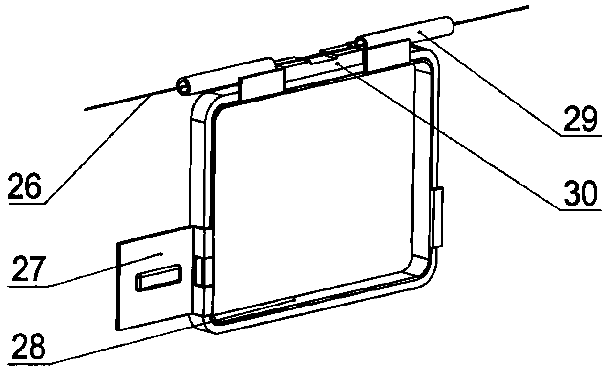
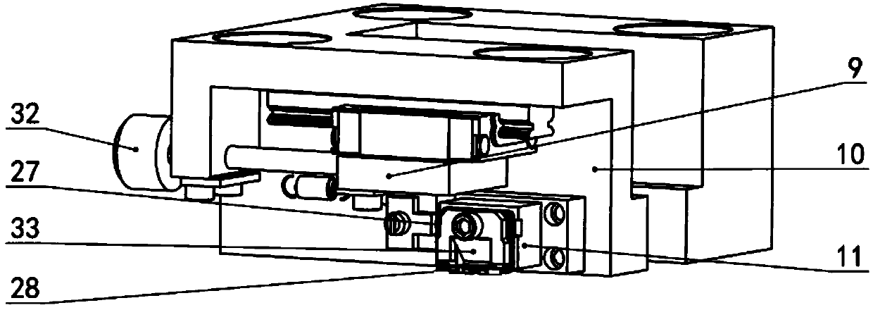
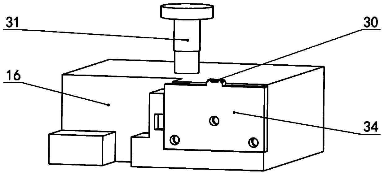
[0029] The device of the present invention is specifically as Figure 5a , Figure 5b , Figure 5c , Figure 5d and Figure 5e As shown, before assembly, the pendulum frame 28 of the parts to be assembled is first installed and clamped on the pendulum frame mounting seat 11 of the upper fixture tool 10, and the eddy current sheet 27 is clamped on the eddy current sheet assembly mechanism 9 of the upper fixture tool 10; The tube 29 and the lug 30 are respectively clamped on the glass tube fixture 15 and the lug fixture 34 of the lower fixture tool 16; Adjust the installation position of the module and complete the clamping of the parts to be assembled.

[0030] The posture of the parts to be assembled is adjusted through the relative posture information obtained by the visual measurement module, so as to meet the assembly accuracy require...


PUM


Abstract

The invention belongs to the technical field of aerospace inertia device precise assembling and relates to a cross-scale part automatic assembling device and method of a weak rigidity framework type structure, and it is an automatic assembling technology used for microminiature accelerometer inertial pendulum assemblies. The device is mainly composed of a vision measuring module, an upper installing adjustment module, a lower installing adjustment module and wire penetrating self-aligning modules; the upper installing adjustment module and the lower installing adjustment module are on the middle portion; the wire penetrating self-alignment modules are located on the two sides of the lower installing adjustment module; and the vision measuring module is located on the front side. The cross-scale part automatic assembling device and method of the weak rigidity framework type structure overcome the precision and efficiency defect caused by a current pendulum assembly assembling process, and can achieve alignment positioning of vortex pieces, automatic adjusting and assembling of relative positions of a pendulum framework and a lug plate and a glass pipe, and automatic penetrating in,centering adjustment and fixation of a suspended wire relative to the glass pipe, the tensile force is controllable, a clamp tool can be disassembled and assembled as a whole, and a part keeps an assembly position after disassembling. The device is composed of the vision measuring module, the upper installing adjustment module, the lower installing adjustment module and the wire penetrating self-aligning modules.

Description

technical field [0001] The invention belongs to the technical field of precise assembly of aerospace inertial devices, relates to a weak steel frame structure cross-scale automatic assembly device and method, and is an automatic assembly technology for micro-miniature accelerometer inertial pendulum components. Background technique [0002] Accelerometers are the core sensitive components of inertial navigation and inertial guidance systems, and are widely used in navigation systems in aviation, aerospace and other fields. Suspended wire pendulum accelerometer is small in size, light in weight, large in measuring range, has high precision and can withstand large acceleration and impact. As the feedback element in the servo loop of the pendulum accelerometer, the torquer is mainly used to make the closed-circuit system of the accelerometer work in a state of torque balance. The performance of the torquer has a great influence on the accuracy of the accelerometer. The pendulu...

Claims


Application Information

Patent Timeline
Patent Type & Authority Applications(China)
IPC IPC(8): B23P19/00
CPCB23P19/00
Inventor 王晓东任同群徐向东唐玲莉李伟钱志龙刘指柔王晓飞
Owner DALIAN UNIV OF TECH
Learn More