
Optical fiber temperature and vibration series integrated sensor based on blazed grating and optical fiber grating

A technology of blazed gratings and fiber gratings, applied in the direction of thermometers, instruments, thermometers, etc. that change physically/chemically, can solve the problems of difficult structure assembly, troublesome maintenance, zero point offset, etc., and achieve strong anti-electromagnetic interference ability and reliable connection The effect of high stability and small zero drift

Inactive Publication Date: 2019-03-22
NINGBO CRRC TIMES TRANSDUCER TECH CO LTD
View PDF7 Cites 1 Cited by
  • Summary
  • Abstract
  • Description
  • Claims
  • Application Information

AI Technical Summary

Problems solved by technology

[0005] (1) Acceleration is measured through piezoelectric crystals. Charge accumulation will occur on the surface of piezoelectric crystals. Long-term use will cause zero point offset. Regular sensor maintenance, charge release and recalibration are required, which will bring great trouble to maintenance. trouble
[0006] (2) Affected by electromagnetic interference, sampling accuracy, etc., the ability to detect weak signals is poor. At the same time, there is strong vibration in the train operating environment, and the vibration of the cable will bring electrical noise coupling, which aggravates this effect and leads to the measurement accuracy of the sensor. poor
[0007] (3) Solder joints in the prior art are prone to failure due to vibration
[0008] (4) The connector is prone to failure due to water ingress, oxidation, etc.
[0009] (5) Large volume and difficult structure assembly

Method used


Image

  • Optical fiber temperature and vibration series integrated sensor based on blazed grating and optical fiber grating
  • Optical fiber temperature and vibration series integrated sensor based on blazed grating and optical fiber grating
  • Optical fiber temperature and vibration series integrated sensor based on blazed grating and optical fiber grating

Examples


Embodiment Construction

[0043] The following are specific embodiments of the present invention and in conjunction with the accompanying drawings, the technical solutions of the present invention are further described, but the present invention is not limited to these embodiments.

[0044] Combine below Figure 1 to Figure 9 The technical solution provided by the present invention is described in more detail.

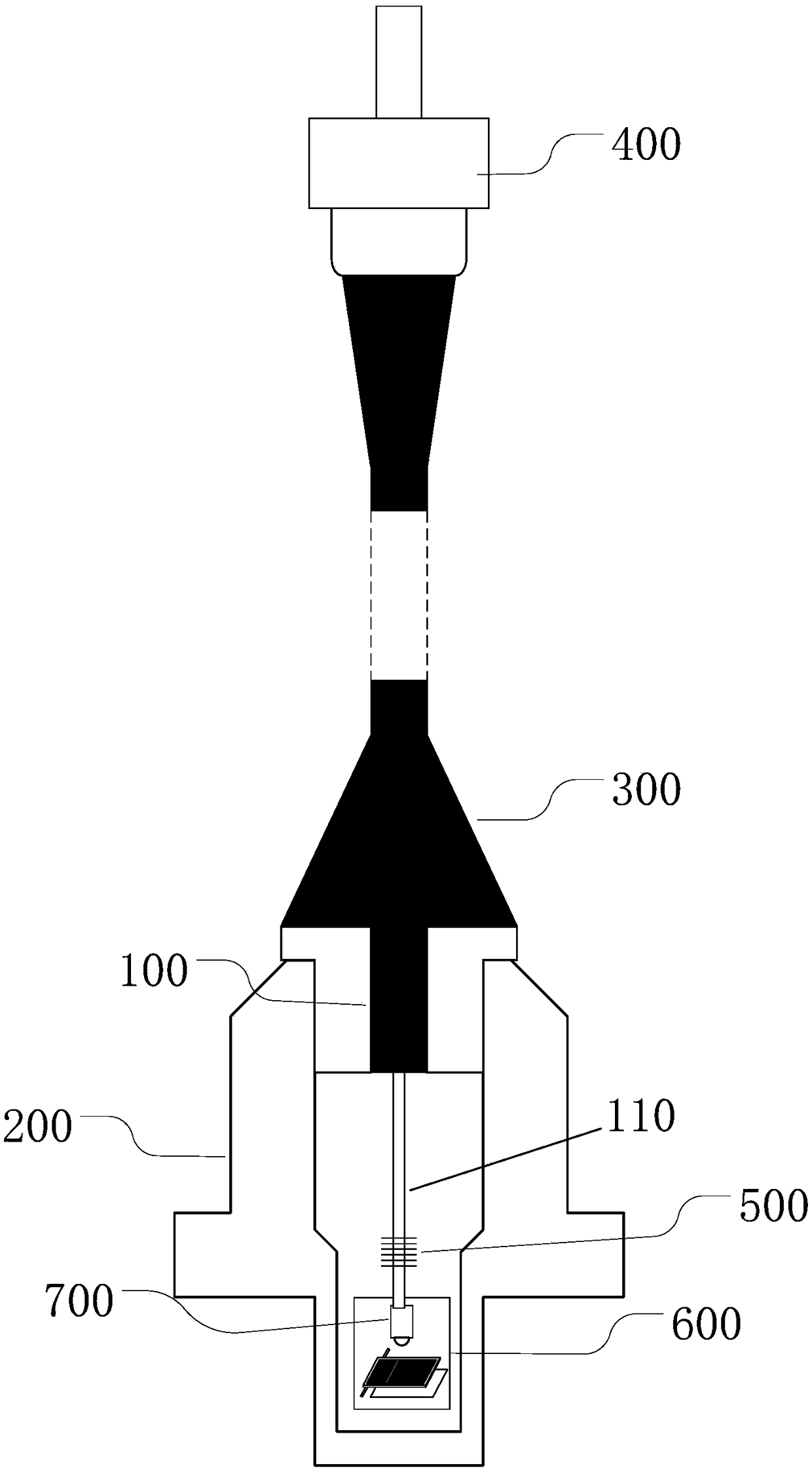
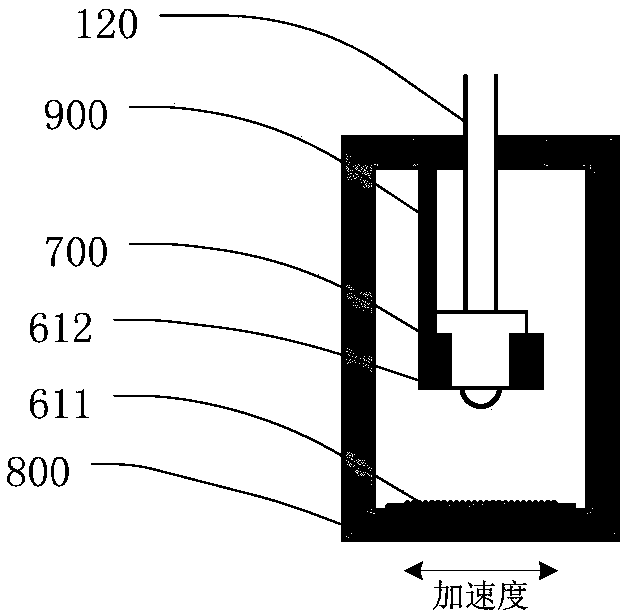
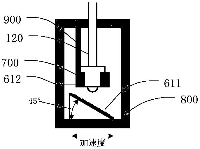
[0045] like Figure 1 to Figure 9 As shown, this optical fiber temperature vibration series integrated sensor based on blazed grating and fiber grating includes:

[0046] A housing, the fiber grating and the blazed grating vibration measurement structure are arranged inside;

[0047] An optical cable, one end of which extends into the housing and leads out a path of optical fiber, respectively the path of optical fiber and the path of optical fiber, the fiber grating is engraved on the path of optical fiber, and the blazed grating vibration measurement structure is connected to the path of op...


PUM


Abstract

The invention provides an optical fiber temperature and vibration series integrated sensor based on a blazed grating and an optical fiber grating. The sensor is used for solving the problems that in the prior art, a temperature and vibration integrated sensor is large in zero drift, needs regular maintenance and calibration and is poor in sampling precision. The sensor comprises a shell and a cable, wherein the shell is internally provided with the optical fiber grating and a blazed grating vibration measuring structure; one end of the cable extends into the shell and leads out a path of optical fiber, the optical fiber grating is engraved on the upper portion of the path of optical fiber, and the blazed grating vibration measuring structure is connected with the tail end of optical fiber.The sensor is small in size, simple in structure assembly, small in zero drift, high in electromagnetic interference resistance, free of electric noise, high in measurement precision and high in connection reliability.

Description

technical field [0001] The invention belongs to the technical field of temperature and vibration integrated sensors, in particular to an optical fiber temperature and vibration series integrated sensor based on blazed gratings and optical fiber gratings. Background technique [0002] Rail rolling stock needs to monitor the running status of bearings, gearboxes, motors and other components through integrated temperature and vibration sensors. Due to the high temperature of the detected part, the existing sensors generally use the piezoelectric principle for acceleration monitoring and platinum resistance for temperature monitoring. [0003] For example, the Chinese patent whose publication number is CN01233313 discloses a temperature vibration digital-analog composite sensor, in which a digital temperature sensitive device, a piezoelectric chip and a circuit board are packaged in the sensor housing, and the circuit board is characterized in that the circuit board contains a p...

Claims


Application Information

Patent Timeline
Patent Type & Authority Applications(China)
IPC IPC(8): G01H9/00G01K11/32G01K11/3206
CPCG01H9/004G01K11/32
Inventor 郑良广赵呈锐杨达金波吴明明
Owner NINGBO CRRC TIMES TRANSDUCER TECH CO LTD
Learn More