Dual reinforcing ring of marine large liquefied gas storage tank and construction scheme of dual reinforcing ring

A technology for liquefied gas storage tanks and reinforcement rings, which is applied in metal processing equipment, fixed-capacity gas storage tanks, gas/liquid distribution and storage, etc., and can solve the problems of not being able to meet the structural strength requirements of large liquid tanks and increasing volume. Relieve the pressure of site layout and hoisting and transportation, improve manufacturing efficiency and facilitate use

Pending Publication Date: 2019-03-22
江苏华滋能源工程有限公司
View PDF6 Cites 1 Cited by
  • Summary
  • Abstract
  • Description
  • Claims
  • Application Information

AI Technical Summary

Problems solved by technology

[0003] The purpose of the present invention is to provide a double-channel reinforcement ring for a large-scale liquefied gas storage tank for ships and its construction scheme in order to solve the above problems, which solves the problem of increasing the corresponding volume in order to meet the market needs and the increasingly stringent discharge requirements. , resulting in the structure of the entire liquefied gas storage tank being several times larger than the previous size, the traditional single-channel reinforcement ring can no longer meet the structural strength requirements of large liquid tanks

Method used


Image

  • Dual reinforcing ring of marine large liquefied gas storage tank and construction scheme of dual reinforcing ring
  • Dual reinforcing ring of marine large liquefied gas storage tank and construction scheme of dual reinforcing ring
  • Dual reinforcing ring of marine large liquefied gas storage tank and construction scheme of dual reinforcing ring

Examples


Embodiment Construction

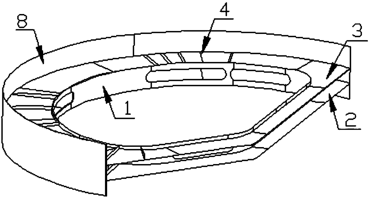
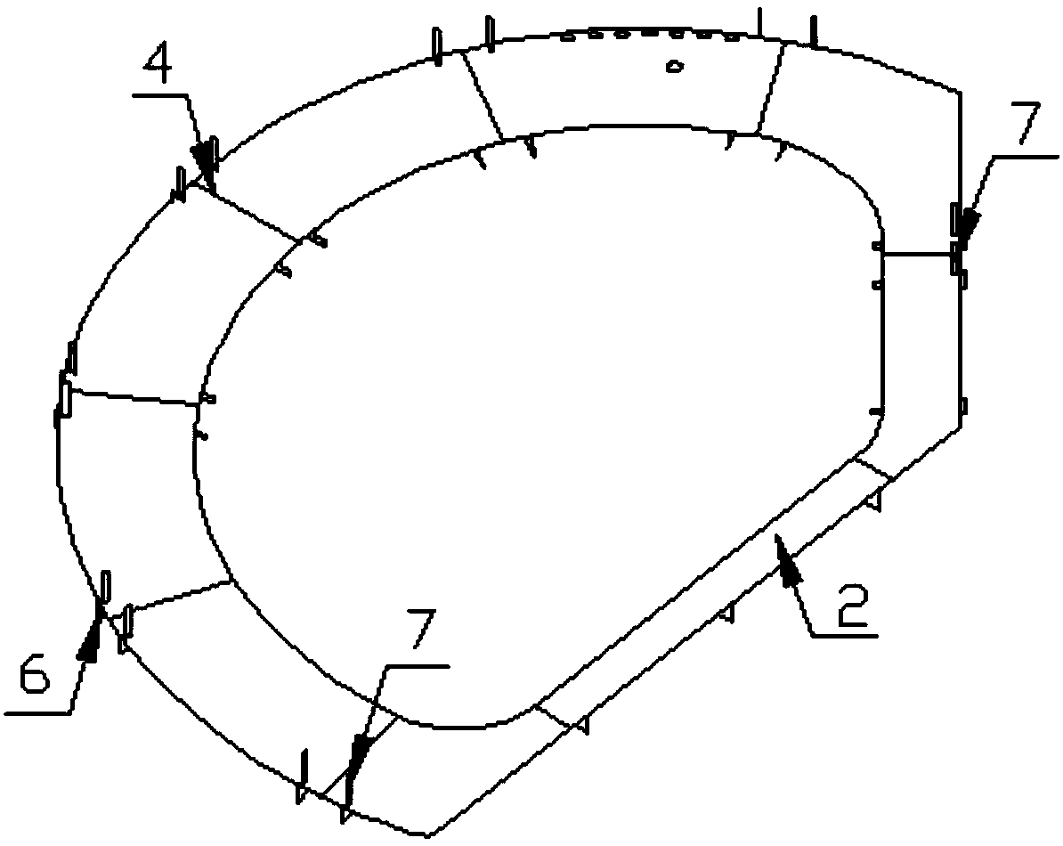
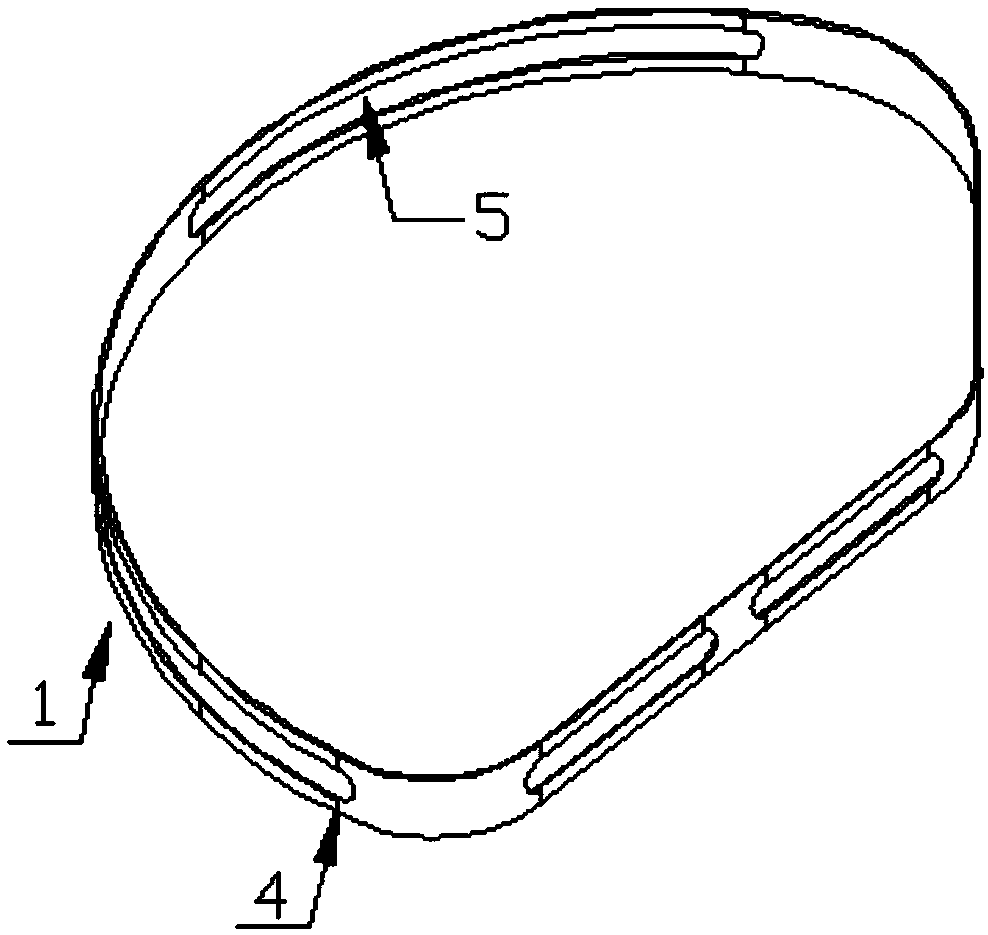
[0031] Such as Figure 1-7 As shown, this specific embodiment adopts the following technical solutions: a double-channel reinforcement ring for a large-scale liquefied gas storage tank for ships, including a panel 1, a web and a rib 4, the panel 1 is provided with a web, and the web is provided with Two layers, the web includes the bow web 2 and the stern web 3, the bow web 2, the stern web 3 and the panel 1 form a reinforced ring structure, and the bow web 2 and the stern web 3 are provided with The mounting holes corresponding to the outline of the panel 1, the bow web 2, the stern web 3 and the panel 1 are provided with stiffeners 4, and the panel 1 between the bow web 2 and the stern web 3 is provided with A plurality of round holes 5, the outer bottom of the bow web 2 is provided with a mounting frame 6, the top of the outer edge of the bow web 2 is provided with a cam 7, and the mounting frame 6 is set correspondingly to the cam 7 A casing 8 is installed on the outer ed...


PUM

PropertyMeasurementUnit
lengthaaaaaaaaaa
widthaaaaaaaaaa
widthaaaaaaaaaa

Abstract

The invention discloses a dual reinforcing ring of a marine large liquefied gas storage tank. The dual reinforcing ring comprises a panel, web plates and reinforcing ribs. The two layers of web platesare arranged, the web plates comprise the bow web plate and the stern web plate, and a reinforcing ring structure is formed by the bow web plate, the stern web plate and the panel. Mounting holes corresponding to the outline of the panel are formed in the bow web plate and the stern web plate. The reinforcing ribs are arranged on the bow web plate, the stern web plate and the panel. Multiple kidney-shaped holes are formed in the part, between the bow web plate and the stern web plate, of the panel. Mounting bed jigs are arranged at the bottom of the outer edge of the bow web plate, and clampsare arranged at the top of the outer edge of the bow web plate. The dual reinforcing ring is reasonable and simple in structure and convenient to use; the yield strength and dynamic loads of the reinforcing ring are greatly improved, the emergence of the ultra-large liquefied gas storage tank becomes real from the paper; and by means of the structural characteristics of the storage tank, the production process is optimized, the number of times of turnover of the structure is effectively reduced, the segmented manufacturing efficiency is greatly improved, and meanwhile consumption of manpowerand resources is reduced from the cost.

Description

Technical field: [0001] The invention relates to the technical field of construction of a C-type liquefied gas storage tank, in particular to a double-channel reinforcement ring for a large-scale marine liquefied gas storage tank and a construction scheme thereof. Background technique: [0002] The increasing demand for liquefied natural gas in the market has put forward higher and higher requirements for the volume of liquefied gas carriers currently in operation. In order to meet the needs of the market, the super large C-type liquefied gas storage tank was born. Compared with the small C-type liquefied gas storage tank, the volume has increased by 3-4 times. Not only the efficiency is greatly improved, but also more economical and clean. Catering to market needs and increasingly stringent emission requirements, the corresponding increase in volume has resulted in the structure of the entire liquefied gas storage tank being several times larger than before. The traditional...

Claims


Application Information

Patent Timeline
Patent Type & Authority Applications(China)
IPC IPC(8): F17C1/00F17C1/02F17C13/00B23K31/02
CPCF17C1/002F17C1/02F17C13/002B23K31/02F17C2209/221
Inventor 王瑞永镇杰石峰磊
Owner 江苏华滋能源工程有限公司
Why Eureka
Try Eureka