Oil temperature control system of forming machine

A control system and oil temperature technology, applied in the direction of presses, manufacturing tools, etc., can solve the problems of lack of cooling oil state and temperature, difficult detection of built-in cooling system, frequent inspection and detection of oil temperature data, etc., to achieve automatic operation , Reduce operating costs, facilitate maintenance and maintenance

Pending Publication Date: 2019-03-22
CHONGQING LONGYU PRECISION COPPER TUBE CO LTD
View PDF0 Cites 0 Cited by
  • Summary
  • Abstract
  • Description
  • Claims
  • Application Information

AI Technical Summary

Problems solved by technology

[0003] In view of the above-mentioned deficiencies in the prior art, the main purpose of the present invention is to solve the problem of lack of corresponding monitoring equipment for the state and temperature of the cooling oil in the current molding machine equipment, and introduce a molding machine that can automatically detect the oil temperature in real time. Oil temperature control system
[0005] The innovation of the present invention lies in the innovative use of an external oil temperature cooling device in this field, which solves the problems of difficult detection and maintenance of the built-in cooling system. The automatic control, which has never been involved in this field before, solves the problem that operators need to frequently inspect and detect oil temperature data, and can realize automatic control and intelligent adjustment, which is conducive to the automatic operation of the production line, which has great practical significance

Method used


Image

  • Oil temperature control system of forming machine
  • Oil temperature control system of forming machine
  • Oil temperature control system of forming machine

Examples


Embodiment Construction

[0021] The present invention will be further described below in conjunction with the accompanying drawings and specific embodiments.

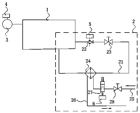
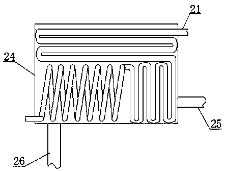
[0022] like Figure 1-Figure 2 As shown, a molding machine oil temperature control system of the present invention includes an oil tank 1 containing drawing oil, and an oil temperature cooling device 2 is installed outside the oil tank 1, and the oil temperature cooling device 2 includes an oil circulation pipe One end of the oil circulation pipeline 21 communicates with the oil tank 1, a gear pump 22 and a first control valve 23 are installed on the oil circulation pipeline 21, and the gear pump 22 is installed on the first control valve 23 The front end of the first control valve 23 is also equipped with a cooler 24, and the other end of the oil circulation line 21 passes through the cooler 24 and communicates with the oil tank 1 to form a circuit; on the cooler 24 The water inlet pipe 25 and the water outlet pipe 26 are respectively connect...


PUM


Abstract

The invention relates to an oil temperature control system of a forming machine. The oil temperature control system comprises an oil tank, wherein the oil tank is filled with drawing oil, an oil temperature cooling device is installed on the outer side of the oil tank, the oil temperature cooling device comprises an oil circulating pipeline, one end of the oil circulating pipeline communicates with the oil tank, a gear pump and a first control valve are installed on the oil circulating pipeline, the gear pump is installed on the front end of the first control valve, a cooler is further installed on the back end of the first control valve, and the other end of the oil circulating pipeline passes through the cooler and then communicates with the oil tank so as to form a loop; a water inlet pipe and a water outlet pipe are respectively connected to the cooler, an electromagnetic valve and a second control valve are installed on the water inlet pipe, and cooling water enters from the waterinlet pipe and passes through the second control valve, the electromagnetic valve and the cooler and then flows out from the water outlet pipe; and an oil temperature monitoring meter which is used for monitoring the temperature of the oil is further installed on the oil tank. The oil temperature control system has the advantages of convenience in periodical maintenance and service, no need of real-time guard of personnel and good reliability.

Description

technical field [0001] The invention relates to high-precision copper tube processing equipment, in particular to an oil temperature control system for a forming machine, which belongs to the technical field of copper tube processing. Background technique [0002] In the process of making high-precision copper tubes, forming machine equipment is needed, which is used to prefabricate and shape copper tube blanks, and then transport the preformed copper tubes to the next equipment for subsequent operations. In the process of using the molding machine, a large amount of heat will be generated due to operations such as extrusion and drawing. In order to ensure the stable operation of the molding machine equipment, it is necessary to configure a cooling system in the molding machine to reduce the oil temperature. However, the cooling system in the current molding machine equipment is a sleeve-type heat exchanger. The cooling system is directly placed inside the fuel tank. Its str...

Claims


Application Information

Patent Timeline
Patent Type & Authority Applications(China)
IPC IPC(8): B21C9/00B30B15/26
CPCB21C9/00B30B15/26
Inventor 李红安罗海潮李君铭李光辉谢泳殷洪林张德志常俊杰
Owner CHONGQING LONGYU PRECISION COPPER TUBE CO LTD
Why Eureka
Try Eureka