
Display panel and display device

A display panel and display area technology, which is applied in the direction of identification devices, instruments, etc., can solve the problems of uneven display, different loads, and different lengths of the display panel, and achieve the effects of uniform display, reduced delay difference, and reduced load difference

Active Publication Date: 2019-03-19
SHANGHAI TIANMA MICRO ELECTRONICS CO LTD
View PDF11 Cites 2 Cited by
  • Summary
  • Abstract
  • Description
  • Claims
  • Application Information

AI Technical Summary

Problems solved by technology

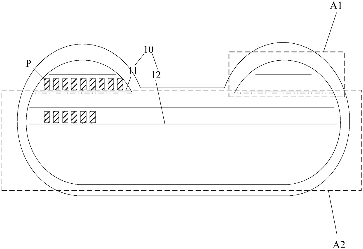
[0002] In order to meet the needs of different occasions, display panels with special shapes have emerged as the times require, and the shapes of such display panels are often different from the current rectangular display panels. figure 1 The display panel shown is taken as an example. Since this kind of display panel includes two smaller first display areas A1 and one larger second display area A2, the grid lines 11 located in the first display area A1 and the grid lines located in the second display area A1 The lengths of the gate lines 12 in the two display areas A2 are different; and, due to the difference in length of each gate line 10, the number of pixel units P electrically connected to each gate line 10 is also different, and the resistance of each gate line 10 is different. Different, the coupling capacitance between each gate line 10 and other electrodes (such as data lines) will also be different, and then the load of each gate line 10 will be different, resulting in inconsistent voltage drop (feedthrough) of each gate line 10 with different lengths. resulting in uneven display of the display panel

Method used


Image

  • Display panel and display device
  • Display panel and display device
  • Display panel and display device

Examples


Embodiment Construction

[0025] The specific implementation manners of a display panel and a display device provided by the embodiments of the present invention will be described in detail below with reference to the accompanying drawings. It should be noted that the described embodiments are only some of the embodiments of the present invention, but not all of the embodiments. Based on the embodiments of the present invention, all other embodiments obtained by persons of ordinary skill in the art without making creative efforts belong to the protection scope of the present invention.

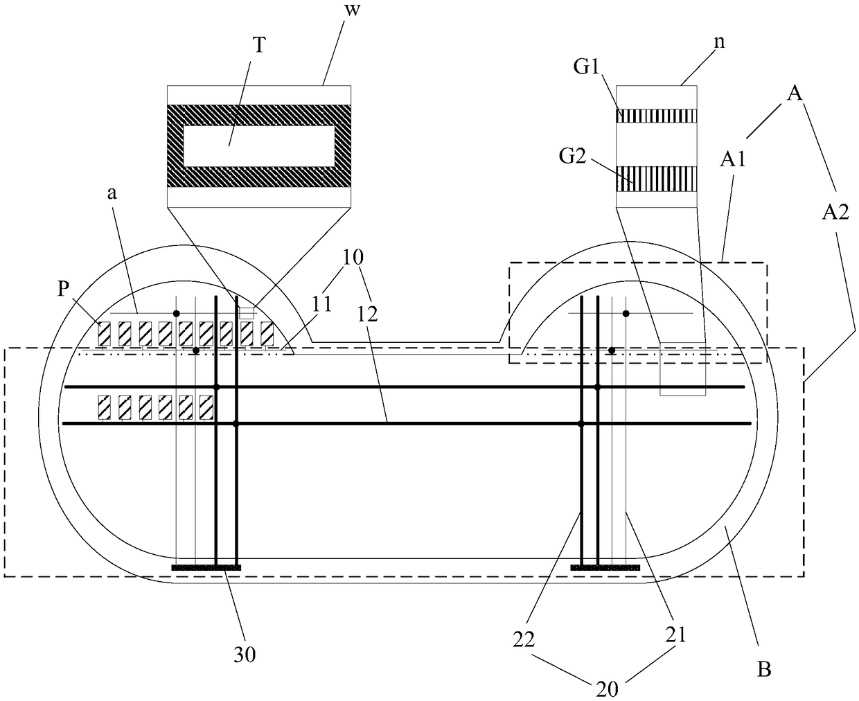
[0026] An embodiment of the present invention provides a display panel, such as Figure 2 to Figure 5 As shown, it may include: a display area A provided with a plurality of pixel units P arranged in an array;

[0027] The display area A includes a first display area A1 and a second display area A2;

[0028] The display area A is provided with a plurality of gate lines 10 arranged in parallel and electrically connect...


PUM


Abstract

The invention discloses a display panel and a display device and relates to the technical field of display. In the embodiment of the invention, by arranging first connecting lines A and first connecting lines B, namely when each first grid line is electrically connected with at least one first connecting line A transmitting grid electrode scanning signals and each second grid line is electricallyconnected with at least two first connecting line B transmitting same grid electrode scanning signals, the width of the first connecting lines A is set to be smaller than that of the first connectinglines B. Therefore, decrease of load difference of first grid lines and second grid lines can be facilitated, thus the delay difference of the first grid lines and the second grid lines is decreased,display of the display panel is more uniform, and accordingly the display effect of the display panel is improved.

Description

technical field [0001] The invention relates to the field of display technology, in particular to a display panel and a display device. Background technique [0002] In order to meet the needs of different occasions, display panels with special shapes have emerged as the times require, and the shapes of such display panels are often different from the current rectangular display panels. figure 1 The display panel shown is taken as an example. Since this kind of display panel includes two smaller first display areas A1 and one larger second display area A2, the grid lines 11 located in the first display area A1 and the grid lines located in the second display area A1 The lengths of the gate lines 12 in the two display areas A2 are different; and, due to the difference in length of each gate line 10, the number of pixel units P electrically connected to each gate line 10 is also different, and the resistance of each gate line 10 is different. Different, the coupling capacitan...

Claims


Application Information

Patent Timeline
Patent Type & Authority Applications(China)
IPC IPC(8): G09F9/30
CPCG09F9/30
Inventor 刘胜优许传志
Owner SHANGHAI TIANMA MICRO ELECTRONICS CO LTD
Learn More