
Safe and reliable rapid rescue device and rescue method after tunnel collapse

A tunnel and safety technology, applied in safety devices, earthwork drilling, mining equipment, etc., can solve problems such as single support means, increased rescue time, and long excavation time, so as to ensure life safety and save rescue costs , the effect of shortening the rescue time

Active Publication Date: 2020-08-25
NORTHEASTERN UNIV LIAONING
View PDF4 Cites 1 Cited by
  • Summary
  • Abstract
  • Description
  • Claims
  • Application Information

AI Technical Summary

Problems solved by technology

[0004] (1) Ordinary rescue uses manual excavation, or calls some large machinery such as excavators. It takes a long time to excavate with manual and such machinery. At the same time, the excavation of large machinery requires a good working environment. If the limit is too large, the rescue operation cannot be carried out, and the lives of the trapped persons are threatened
[0005] (2) General rescue will carry out temporary support after excavating the escape channel. The support method is single, which is likely to cause a secondary collapse, and cannot safely and reliably guarantee the life safety of the rescuers. At the same time, after the rescue, many support methods The structure needs to be demolished, which consumes a lot of manpower and financial resources
[0006] (3) Before the rescue, it is necessary to carry out a large number of exploration designs and formulate a feasible rescue plan. At the same time, the construction is also difficult, which undoubtedly increases the rescue time and seriously affects the life safety of the trapped people.
[0007] (4) How to transport the wounded reasonably and effectively when carrying out rescue after the collapse of the tunnel has also become a problem. It is often difficult to transport the wounded out of the trapped place due to environmental constraints

Method used


Image

  • Safe and reliable rapid rescue device and rescue method after tunnel collapse
  • Safe and reliable rapid rescue device and rescue method after tunnel collapse
  • Safe and reliable rapid rescue device and rescue method after tunnel collapse

Examples


Embodiment 1

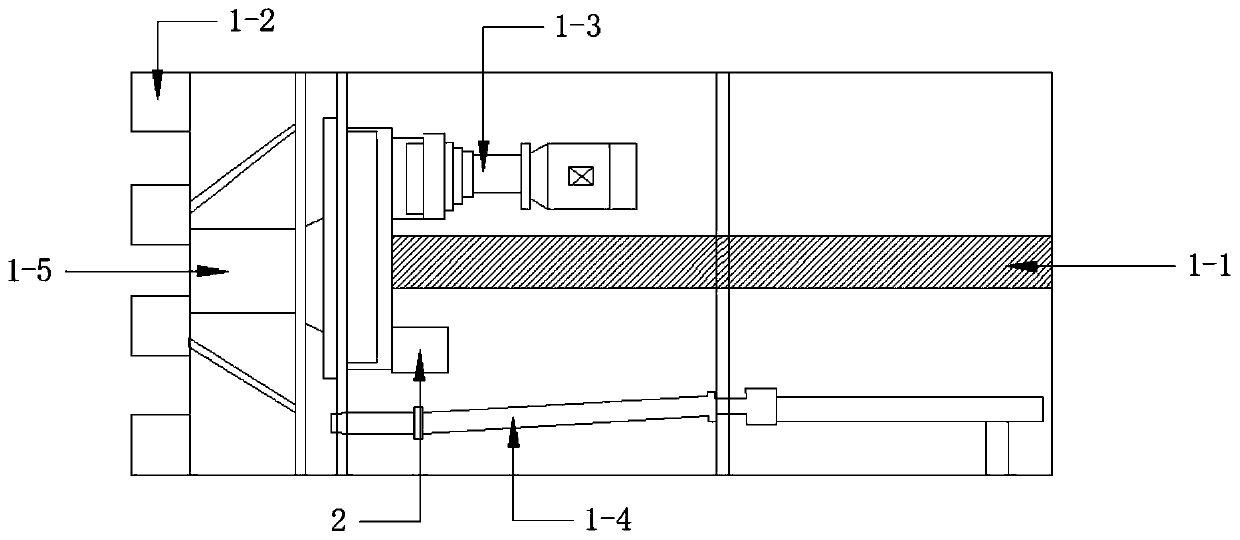
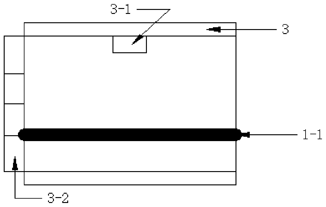
[0050] Such as figure 1 As shown, a safe and reliable rapid rescue device after a tunnel collapse includes a pipe jacking machine 1 with a built-in belt conveyor, a radar life detector 2, a steel pipe jacking 3 with a built-in lighting device, and a jack 4, wherein:

[0051] Such as figure 2 As shown, the pipe jacking machine 1 with built-in belt conveyor includes rotary excavation system 1-2, main top hydraulic propulsion system 1-3, soil conveying system 1-4 and belt conveyor 1-1, main top hydraulic propulsion The system 1-3 advances the rotary excavation system 1-2 to excavate in the tunnel, and the head of the rotary excavation system 1-2 is provided with a hatch 1-5 that opens into the pipe jacking machine, and the hatch 1-5 is facing the pipe jacking The built-in belt conveyor 1-1 is convenient for transporting the injured; the soil conveying system 1-4 is connected to the rotary excavation system 1-2, and transports the excavated earth during the excavation process of...


PUM


Abstract

The invention relates to a safe and reliable rapid rescuing device and method after tunnel collapse. The rapid rescuing device comprises a built-in belt conveyor tube push bench, a radar life detection instrument, a built-in illumination device steel push tube and a jack. After tunnel collapse, a working well is rapidly dug, the built-in belt conveyor tube push bench, the radar life detection instrument, the built-in illumination device steel push tube and the jack are arranged inside the working well, then, excavation rescuing is performed on the built-in belt conveyor tube push bench, the radar life detection instrument detects the life sign inside collapse ruins, the rescue position can be rapidly and accurately reached, and then, a trapped person is conveyed out through the belt type conveyor from a rescue channel formed by the built-in belt conveyor tube push bench and the built-in illumination device steel push tube. After collapse during tunnel construction, the device is safe,reliable and capable of achieving rapid rescuing.

Description

technical field [0001] The invention relates to the technical field of underground research of civil engineering such as soil excavation and tunnel excavation, and specifically relates to a safe and reliable rapid rescue device and rescue method after tunnel collapse, which can be safe, reliable and fast after tunnel collapse occurs. rescue. Background technique [0002] Nowadays, in order to make better use of underground space and effectively protect the ecological environment on the ground, people are vigorously developing underground space technology, developing and utilizing space resources below the ground, and building underground houses and underground structures, including road tunnels, water Underground tunnels, underground railways, pipe galleries and underground crossings and other underground buildings. Due to various influences such as construction reasons, design reasons, and complex geological conditions, the collapse of the tunnel has become an important is...

Claims


Application Information

Patent Timeline
Patent Type & Authority Patents(China)
IPC IPC(8): E21F11/00
CPCE21F11/00
Inventor 李慎刚李天亮夏治康赵文柏谦王云墨张超哲王志国唐瑞兆李伟伟
Owner NORTHEASTERN UNIV LIAONING
Learn More