
Soil rehabilitation and quality improvement equipment

A quality improvement equipment and soil remediation technology, applied in the restoration of contaminated soil, etc., can solve the problems of poor leaching effect and low leaching efficiency

Inactive Publication Date: 2019-03-19
SHANDONG LUNAN GEOLOGICAL ENG SURVEY INST
View PDF7 Cites 7 Cited by
  • Summary
  • Abstract
  • Description
  • Claims
  • Application Information

AI Technical Summary

Problems solved by technology

[0006] In order to overcome the need to manually pull the pipe to spray the soil, the leaching efficiency is low, and the solvent is generally only sprayed on the surface of the soil, so the shortcomings of the poor rinsing effect, the technical problem of the present invention is: to provide a method that can improve Soil remediation and quality improvement equipment that can improve the leaching efficiency, spray the solvent inside the soil, and improve the leaching effect

Method used


Image

  • Soil rehabilitation and quality improvement equipment
  • Soil rehabilitation and quality improvement equipment
  • Soil rehabilitation and quality improvement equipment

Examples


Embodiment 1

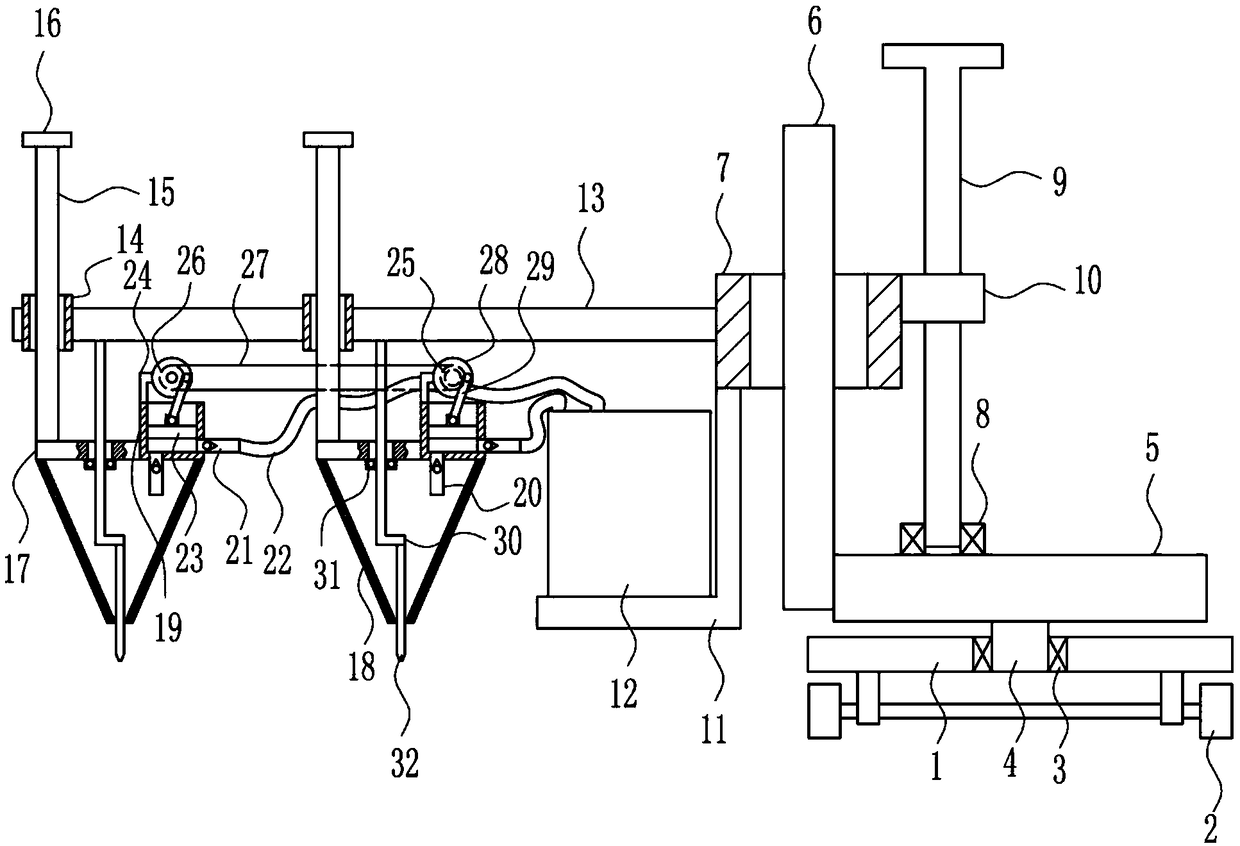
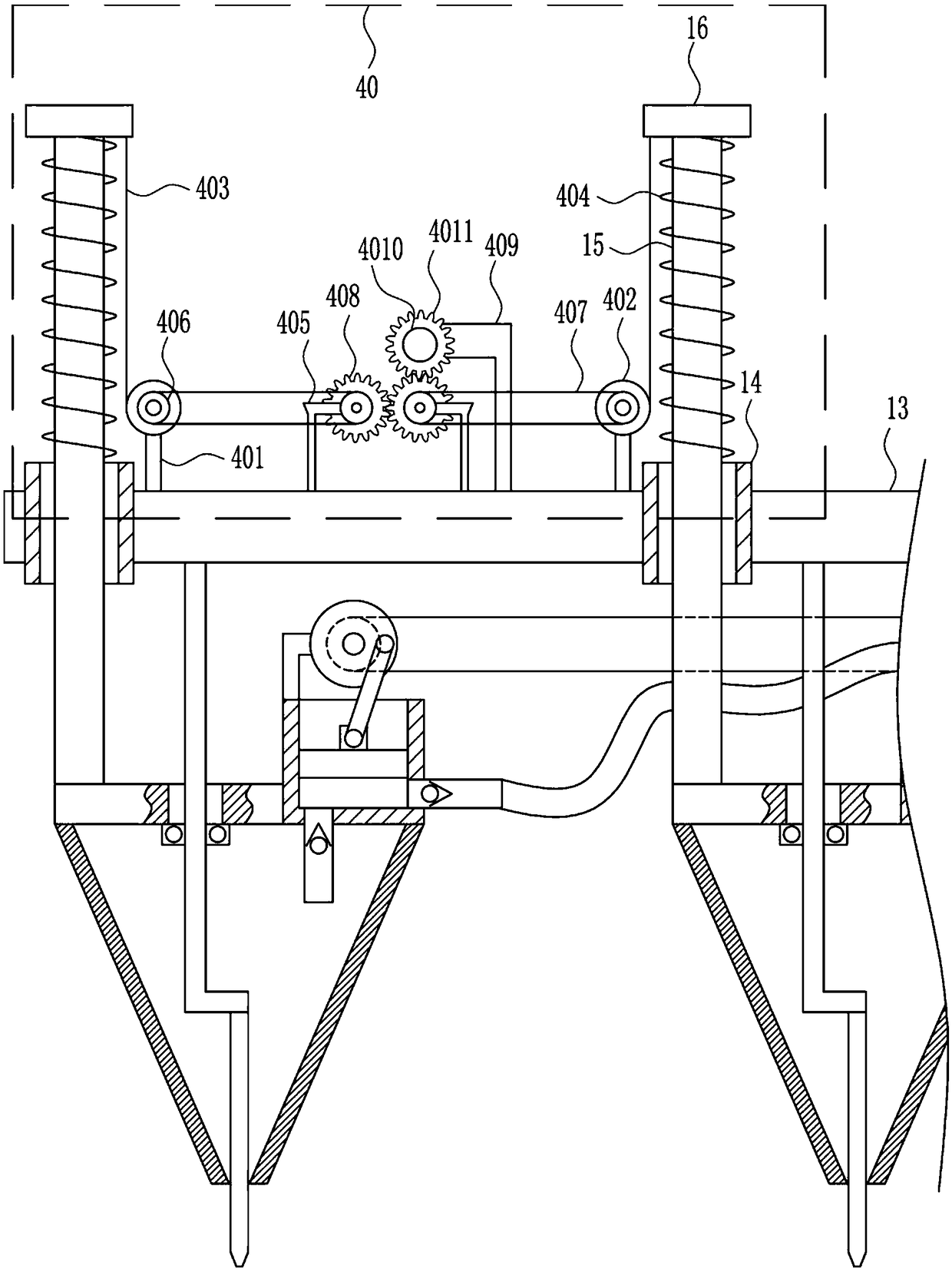
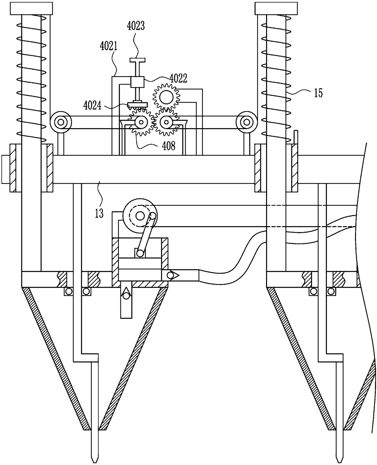
[0026] A kind of equipment for soil restoration and upgrading, such as Figure 1-5 As shown, it includes a bottom plate 1, a vehicle frame 2, a first bearing seat 3, a rotating rod 4, a mounting plate 5, a first guide rail 6, a first guide sleeve 7, a second bearing seat 8, a first screw rod 9, a first A nut 10, an L-shaped plate 11, a material box 12, a connecting plate 13, a second guide sleeve 14, a second guide rail 15, a handle 16, a baffle plate 17, a cone bucket 18, a piston cylinder 19, a first one-way valve 20, Second one-way valve 21, infusion tube 22, piston block 23, L-shaped block 24, first electric wheel 25, first runner 26, first drive bar 27, rotating disk 28, rocking bar 29, the first L-shaped bar 30. The sealing ring 31 and the stop rod 32, the vehicle frame 2 is installed on the lower side of the bottom plate 1, the first bearing seat 3 is connected to the inner middle of the bottom plate 1, the first bearing seat 3 is connected to the rotating rod 4, and th...

Embodiment 2

[0028] A kind of equipment for soil restoration and upgrading, such as Figure 1-5As shown, it includes a bottom plate 1, a vehicle frame 2, a first bearing seat 3, a rotating rod 4, a mounting plate 5, a first guide rail 6, a first guide sleeve 7, a second bearing seat 8, a first screw rod 9, a first A nut 10, an L-shaped plate 11, a material box 12, a connecting plate 13, a second guide sleeve 14, a second guide rail 15, a handle 16, a baffle plate 17, a cone bucket 18, a piston cylinder 19, a first one-way valve 20, Second one-way valve 21, infusion tube 22, piston block 23, L-shaped block 24, first electric wheel 25, first runner 26, first drive bar 27, rotating disk 28, rocking bar 29, the first L-shaped bar 30. The sealing ring 31 and the stop rod 32, the vehicle frame 2 is installed on the lower side of the bottom plate 1, the first bearing seat 3 is connected to the inner middle of the bottom plate 1, the first bearing seat 3 is connected to the rotating rod 4, and the...

Embodiment 3

[0031] A kind of equipment for soil restoration and upgrading, such as Figure 1-5 As shown, it includes a bottom plate 1, a vehicle frame 2, a first bearing seat 3, a rotating rod 4, a mounting plate 5, a first guide rail 6, a first guide sleeve 7, a second bearing seat 8, a first screw rod 9, a first A nut 10, an L-shaped plate 11, a material box 12, a connecting plate 13, a second guide sleeve 14, a second guide rail 15, a handle 16, a baffle plate 17, a cone bucket 18, a piston cylinder 19, a first one-way valve 20, Second one-way valve 21, infusion tube 22, piston block 23, L-shaped block 24, first electric wheel 25, first runner 26, first drive bar 27, rotating disk 28, rocking bar 29, the first L-shaped bar 30. The sealing ring 31 and the stop rod 32, the vehicle frame 2 is installed on the lower side of the bottom plate 1, the first bearing seat 3 is connected to the inner middle of the bottom plate 1, the first bearing seat 3 is connected to the rotating rod 4, and th...


PUM


Abstract

The invention relates to soil rehabilitation equipment, in particular to soil rehabilitation and quality improvement equipment. The soil remediation and quality improvement equipment can improve the leaching efficiency, enable solvent to be sprayed in the soil and improve the leaching effect. According to the technical scheme, the soil rehabilitation and quality improvement equipment comprises a bottom plate, a frame, a first bearing seat, a rotating rod, a mounting plate, a first guiding rail, a first guiding sleeve, a second bearing seat, a first screw rod, a first nut, an L-shaped plate, etc.; the frame is installed on the lower side of the bottom plate; the first bearing seat is connected in the middle of the inner of the bottom plate; the rotating rod is connected in the first bearingseat; the upper end of the rotating rod is connected with the mounting plate; and the left end of the mounting plate is connected with the first guiding rail. A cone bucket of the soil rehabilitationand quality improvement equipment extends into the soil and then sprays eluent, so that the eluent is sprayed into the soil, in this way, the solvent can be sprayed inside the soil, and the leachingeffect can be improved. A collecting device can collect the eluent in the soil, and a positioning sleeve can fix the angle of the mounting plate.

Description

technical field [0001] The invention relates to a soil repairing device, in particular to a soil repairing and upgrading device. Background technique [0002] The soil is originally a natural shelter and purification treatment place for various wastes. The soil accepts pollutants, which does not mean that the soil is polluted. Only when the soil contains too many pollutants, it affects and exceeds the self-purification ability of the soil. , thus producing harmful hygienic and epidemiological effects, which indicate that the soil has been polluted. There are many reasons for soil pollution, such as industrial sludge, agricultural garbage, sewage irrigation, pollutant deposition in the atmosphere, heavy use of mineral fertilizers and pesticides containing heavy metals, and so on. [0003] Chemical leaching, with the help of chemical and biochemical solvents that can promote the dissolution or migration of pollutants in the soil environment, the eluent is injected into the po...

Claims


Application Information

Patent Timeline
IPC IPC(8): B09C1/08B09C1/02
CPCB09C1/02B09C1/08B09C2101/00
Inventor 毛添星
Owner SHANDONG LUNAN GEOLOGICAL ENG SURVEY INST
Learn More