Operating module for motor vehicle

A technology for motor vehicles and motor vehicle transmissions, applied in the direction of convenient operation, components with teeth, electrical components, etc., can solve problems such as target conflicts, and achieve the effect of compact structure

Active Publication Date: 2019-03-15
ZF FRIEDRICHSHAFEN AG
View PDF10 Cites 0 Cited by
  • Summary
  • Abstract
  • Description
  • Claims
  • Application Information

AI Technical Summary

Problems solved by technology

This clearly conflicts with the goal of keeping tolerances small

Method used


Image

  • Operating module for motor vehicle
  • Operating module for motor vehicle
  • Operating module for motor vehicle

Examples


Embodiment Construction

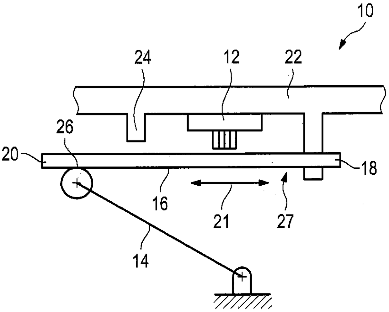
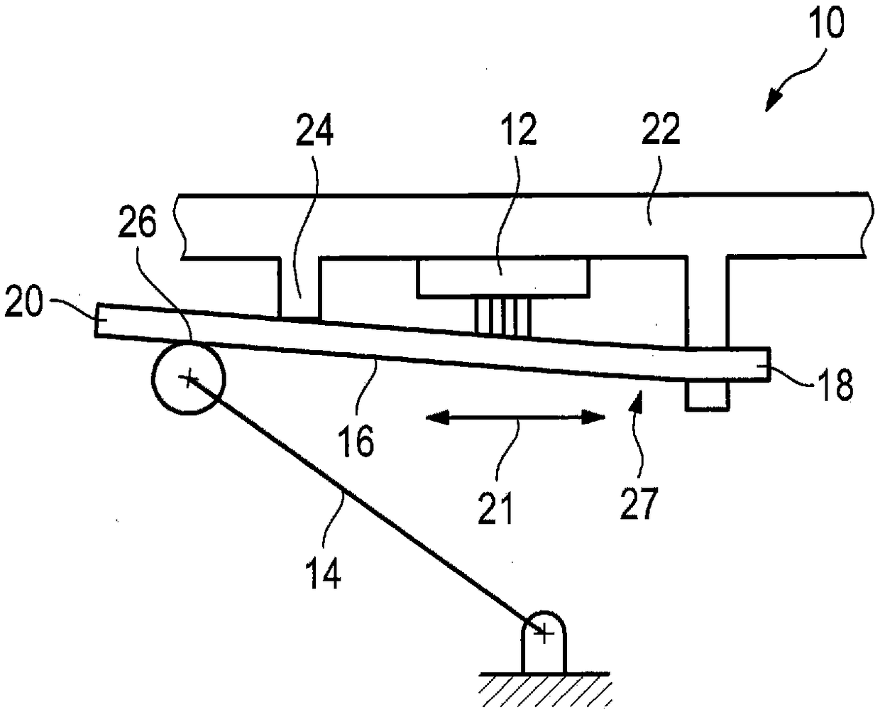
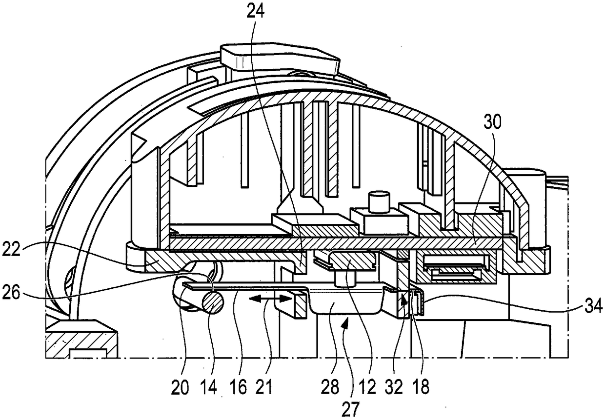
[0030] figure 1 An operating assembly 10 is shown in which an electrical switching element 12 , a microswitch in the illustrated embodiment, is actuated via a first lever 14 and a second lever. The second lever is a leaf spring 16 comprising a fixed clamping end 18 and a free end 20 .

[0031] In the embodiment shown, the first lever 14 can be integrally formed on a shift stage selection element arranged, for example, in the center console of the motor vehicle or on a shift paddle arranged on the steering wheel of the motor vehicle.

[0032] The leaf spring 16 extends in the direction indicated by the arrow 21 .

[0033] In this case, the electrical switching element 12 is supported in a carrier element 22 in which the fixed clamping end 18 of the leaf spring 16 is supported.

[0034] Furthermore, a stop 24 is arranged on the carrier element 22 . The stop is integrally connected to the carrier element 22 and is embodied as a protrusion. The stop portion 24 is used to limit...


PUM


Abstract

Described is an operating module (10) intended for a motor vehicle and comprising an electric switch, in particular for changing drive mode in an automatic motor vehicle transmission. The switch comprises a first, manually actuatable lever (14), a second lever, and an electrical switching element (12). When actuated, the first lever (14) acts on the electrical switching element (12) by way of thesecond lever. The second lever is a leaf spring (16) with a fixedly clamped end (18) and a free end (20). When the first lever (14) is actuated, the leaf spring is deformed in such a way that it is atleast partially shifted in the direction of the switching element (12).

Description

technical field [0001] The invention relates to an operating unit for a motor vehicle, which has an electric switch, in particular for changing the driving stages of an automatic motor vehicle transmission, wherein the switch comprises a manually actuatable first lever, a second A lever and an electrical switching element, and wherein the first lever acts on the electrical switching element via the second lever in its actuated state. Background technique [0002] Operating assemblies with electrical switches are widely used in the motor vehicle sector. These electrical switches are often used to operate radios, navigation systems and / or on-board computers. [0003] A further field of application of the actuating assembly and associated electrical switches is the actuation of motor vehicle transmissions. In this case, the electric switch is preferably used in combination with an automatic motor vehicle transmission. The driver can then manually change or select the drive p...

Claims


Application Information

Patent Timeline
IPC IPC(8): H01H13/18F16H59/02
CPCF16H59/105F16H2059/0247H01H13/186H01H2217/02H01H2235/028H01H17/04H01H2235/024
Inventor 约阿希姆·科赫尔
Owner ZF FRIEDRICHSHAFEN AG
Why Eureka
Try Eureka