An electric motor for a water pump

A technology of electric motors and water pumps, applied in the field of electric motors, can solve the problems of affecting the ecological environment, the normal operation of the fuselage, and the poor heat dissipation performance of the fuselage, and achieve the effect of isolating pollution, good heat dissipation effect, effective and timely heat dissipation

Active Publication Date: 2020-09-22
ZHEJIANG XILING
View PDF6 Cites 0 Cited by
  • Summary
  • Abstract
  • Description
  • Claims
  • Application Information

AI Technical Summary

Problems solved by technology

[0002] At present, most of the existing ordinary oil-immersed motors have excellent sealing performance, but the problem that follows is that the heat dissipation performance inside the fuselage is very poor. For some hot weather areas, these water pump motors are often due to the The internal heat dissipates, causing the internal temperature of the fuselage to be too high, and the normal operation of the fuselage is seriously affected. The service life of the water pump motor is also very short, and if there is oil leakage, it will seriously affect the ecological environment.

Method used


Image

  • An electric motor for a water pump
  • An electric motor for a water pump
  • An electric motor for a water pump

Examples


Embodiment 1

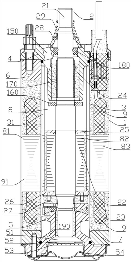
[0027] Embodiment one: if figure 1 As shown, a motor for a water pump includes a casing 1, a rotor assembly 2, a shielding sleeve 3, an upper bearing seat 4, a lower bearing seat 5, an upper end cover 6 and a lower end cover 7; the rotor assembly 2 includes a penetrating The rotor shaft 21 in the casing 1, the rotor 22 sleeved on the rotor shaft 21 and the magnetic steel sleeve 23; the upper bearing seat 4 is arranged on the upper end of the upper end cover 6, and the lower bearing seat 5 is arranged on the lower end cover 7, and a cavity 8 is formed between the casing 1, the upper end cover 6 and the lower end cover 7, and the cavity 8 includes a stator cavity 81 and a rotor cavity 82; the shielding sleeve 3 is sleeved on the rotor The cavity 82 and the shielding sleeve 3 are sleeved on the outside of the rotor assembly 2; the shielding sleeve 3 is formed with an accommodating cavity 31 filled with clean water for heat dissipation.

[0028] The motor of this technical soluti...

Embodiment 2

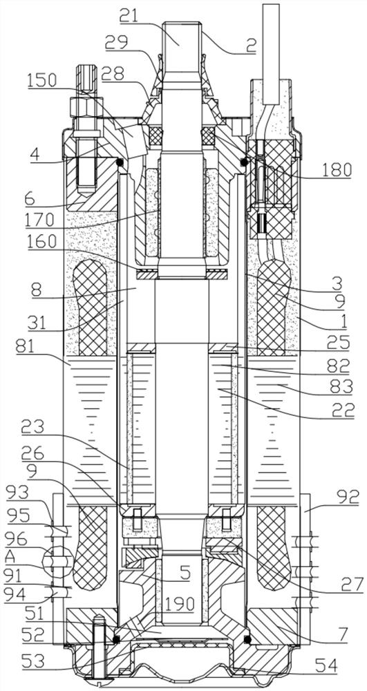
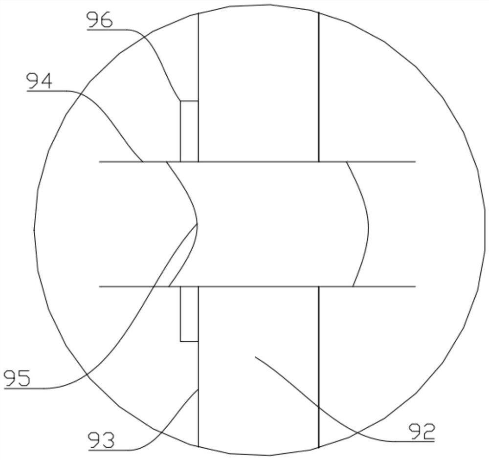
[0045] Embodiment two: if Figure 2-3 As shown, this embodiment is basically the same as Embodiment 1, the difference is that a cavity 92 is formed in the side wall 93 of the sealed cavity 91, and several water pipes passing through the cavity 92 are arranged on the side wall 93 94, one end of the water pipe 94 is located outside the side wall 93, and the other end is located in the sealed cavity 91, and at least one sand-proof filter layer 95 is arranged in the water pipe 94.

[0046] The setting of the water pipe 94 in this technical solution makes the inside of the motor have good ventilation performance, and the heat generated by the motor during operation can be effectively discharged, which solves the problem that the internal heat of the motor cannot be discharged, and the normal operation of the motor is seriously affected due to the high internal temperature. In addition, the anti-sand filter layer 95 in the water pipe 94 can prevent the sand and dust in the water fro...


PUM


Abstract

The invention belongs to the technical field of a water pump, and particularly relates to an electric motor for the water pump. The electric motor comprises a machine shell, a rotor subassembly, a shielding sleeve, an upper bearing seat, a lower bearing seat, an upper end cover and a lower end cover, wherein the rotor subassembly comprises a rotor shaft penetrating in the machine shell, a rotor sleeved on the rotor shaft, and a magnetic steel sleeve; the upper bearing seat is disposed on an upper end of the upper end cover; the lower bearing seat is disposed on a lower end of the lower end cover; a cavity body is formed among the machine shell, the upper end cover and the lower end cover; the cavity body comprises a stator cavity and a rotor cavity; the shielding sleeve is sleeved in the rotor cavity and on an outer side of the rotor subassembly; and an accommodating cavity filled with clear water and used for dissipating heat is formed in the shielding sleeve. An objective of the invention is to provide the electric motor for the water pump with stable structure, good heat dissipation effect and environment-friendliness.

Description

technical field [0001] The invention belongs to the technical field of water pumps, in particular to a motor used for water pumps. Background technique [0002] At present, most of the existing ordinary oil-immersed motors have excellent sealing performance, but the problem that follows is that the heat dissipation performance inside the fuselage is very poor. For some hot weather areas, these water pump motors are often due to the The internal heat dissipates, causing the internal temperature of the fuselage to be too high, and the normal operation of the fuselage is seriously affected. The service life of the water pump motor is also very short, and if there is oil leakage, it will seriously affect the ecological environment. Contents of the invention [0003] The object of the present invention is to provide a motor for water pumps with stable structure, good heat dissipation effect and environmental protection. [0004] The object of the present invention is achieved ...

Claims


Application Information

Patent Timeline
Patent Type & Authority Patents(China)
IPC IPC(8): H02K5/132H02K9/22
CPCH02K5/132H02K9/22
Inventor 杨学良
Owner ZHEJIANG XILING
Why Eureka
Try Eureka