Lighting device for road construction

A lighting device and road construction technology, which is applied in portable lighting devices, lighting devices, lighting auxiliary devices, etc., can solve the problems of inconvenient use and inconvenient portability, and achieve the effects of easy portability, convenient carrying, and convenient installation

Inactive Publication Date: 2019-03-15
芜湖市泽川水利工程有限公司
View PDF4 Cites 2 Cited by
  • Summary
  • Abstract
  • Description
  • Claims
  • Application Information

AI Technical Summary

Problems solved by technology

With this design, although the lamp post is a telescopic structure, the height can be adjusted at will, but it is inconvenient to carry and use

Method used


Image

  • Lighting device for road construction
  • Lighting device for road construction
  • Lighting device for road construction

Examples


specific Embodiment approach

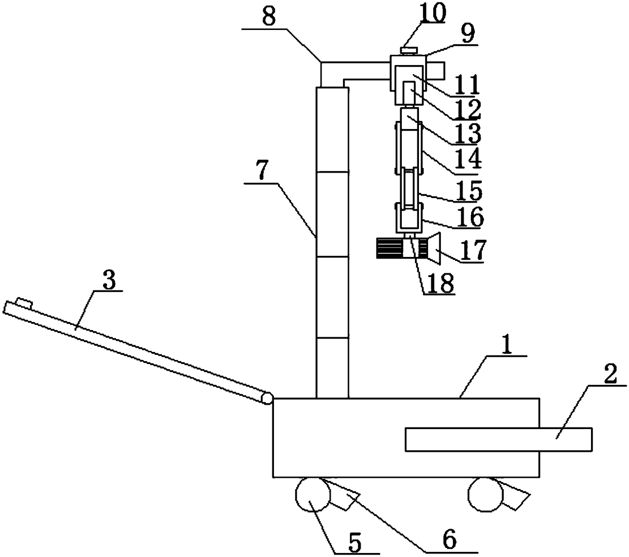
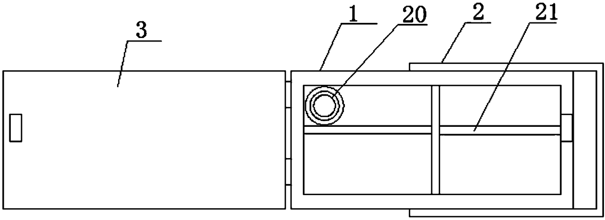
[0022] figure 1 , figure 2 , Figure 5 with Image 6 The specific embodiment of the present invention is shown: a lighting device convenient for road construction, including a box body 1, a handle 2 connected to the box body 1 is provided on the box body 1, and a box body is hinged on the box body 1. Cover 3, the box body 1 is provided with a detachable partition 21, the box body 1 is divided into a plurality of spaces by the partition plate 21, and a fixing seat 20 is arranged in one of the spaces, and the height of the fixing seat 20 is smaller than that of the box body. The height of the body 1, the support rod 7 is detachably connected to the fixed base 20, the support rod 7 is composed of several connecting rods 71, the head and tail of the connecting rods 71 ​​are screwed in turn, the upper end of the support rod 7 An L-shaped support arm 8 is provided, and the L-shaped support arm 8 is threadedly connected with the support rod 7. The L-shaped support arm 8 is provid...

Embodiment 2

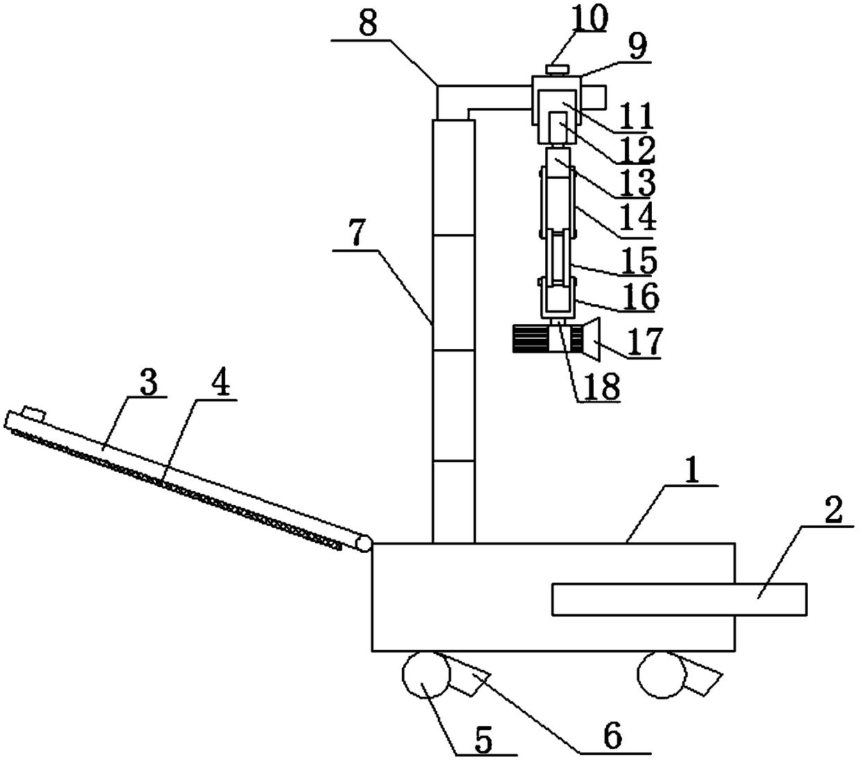
[0028] image 3 , Figure 4 , Figure 5 with Image 6 The specific embodiment of the present invention is shown: a lighting device convenient for road construction, including a box body 1, a handle 2 connected to the box body 1 is provided on the box body 1, and a box body is hinged on the box body 1. Cover 3, the box body 1 is provided with a detachable partition 21, the box body 1 is divided into a plurality of spaces by the partition plate 21, and a fixing seat 20 is arranged in one of the spaces, and the height of the fixing seat 20 is smaller than that of the box body. The height of the body 1, the support rod 7 is detachably connected to the fixed base 20, the support rod 7 is composed of several connecting rods 71, the head and tail of the connecting rods 71 ​​are screwed in turn, the upper end of the support rod 7 An L-shaped support arm 8 is provided, and the L-shaped support arm 8 is threadedly connected with the support rod 7. The L-shaped support arm 8 is provid...


PUM


Abstract

The invention discloses a lighting device for road construction, and relates to the field of road construction illumination. The lighting device comprises a cabinet body, a handle which is rotationally connected with the cabinet body is arranged on the cabinet body, a cabinet cover is hinged to the cabinet body, a detachable partition board is arranged in the cabinet body, the partition plate divides the cabinet body into a plurality of spaces, a fixed base is arranged in one space, a supporting rod is detachably connected to the fixed base, an L-shaped supporting arm is arranged at the upperend of the supporting rod, the L-shaped supporting arm is in threaded connection with the supporting rod, a mounting block is arranged on the L-shaped supporting arm, a box body is arranged on the outer wall of the mounting block, a motor is arranged in the box body, an output shaft of the motor is connected with a connecting block, each of the two side walls of the connecting block is provided with a first connecting rod, the upper ends of the first connecting rods are rotationally connected with the connecting block, the lower ends of the first connecting rods are rotationally connected withsecond connecting rods through rotating shafts, the lower ends of the second connecting rods are rotationally connected with a mounting frame through rotating shafts, and a light with a build-in charging source is arranged at the lower end of the mounting frame. The lighting device is convenient to carry, convenient to install, and, with the illumination angle can be adjusted by 360 degrees, convenience to use.

Description

technical field [0001] The invention relates to the field of road construction lighting, in particular to a lighting device convenient for road construction. Background technique [0002] With the advancement of science and technology, lighting equipment has a variety of styles and functions. When the staff temporarily repairs the road at night, they need the help of lighting equipment. The existing construction lights, the arrangement and installation of the light stand are more troublesome. And random, making the construction site more chaotic, and these lighting equipment, take up a large space, inconvenient to carry, simultaneously the lighting direction is inconvenient to adjust, has brought great inconvenience to people's use. [0003] In view of the above problems, the utility model with the publication number of CN 208139100 U in the prior art discloses a new type of multifunctional on-site construction lamp stand, which includes a rotatable and telescopic light stan...

Claims


Application Information

Patent Timeline
Patent Type & Authority Applications(China)
IPC IPC(8): F21L4/08F21V21/14F21V21/22F21V21/28F21V21/30
CPCF21L4/08F21V21/14F21V21/22F21V21/28F21V21/30
Inventor 叶桂发叶剑汲怀京王媛媛陈健华江春燕
Owner 芜湖市泽川水利工程有限公司
Why Eureka
Try Eureka