On-line Night Vision Thermal Imaging Diagnosis System for Blast Furnace Roof

A diagnostic system and thermal imaging technology, applied in inspection devices and other directions, can solve the problems of inability to monitor temperature and high positioning requirements

Active Publication Date: 2020-07-07
青岛众志测控技术有限公司
View PDF1 Cites 0 Cited by
  • Summary
  • Abstract
  • Description
  • Claims
  • Application Information

AI Technical Summary

Problems solved by technology

[0003] However, although patent No. CN 206188835 U has appeared in the traditional technology, a thermal imaging device for the top of a blast furnace is disclosed. The positioning requirements are high, and the temperature at any point cannot be monitored

Method used


Image

  • On-line Night Vision Thermal Imaging Diagnosis System for Blast Furnace Roof
  • On-line Night Vision Thermal Imaging Diagnosis System for Blast Furnace Roof
  • On-line Night Vision Thermal Imaging Diagnosis System for Blast Furnace Roof

Examples


Embodiment Construction

[0027] The following will clearly and completely describe the technical solutions in the embodiments of the present invention with reference to the accompanying drawings in the embodiments of the present invention. Obviously, the described embodiments are only some, not all, embodiments of the present invention.

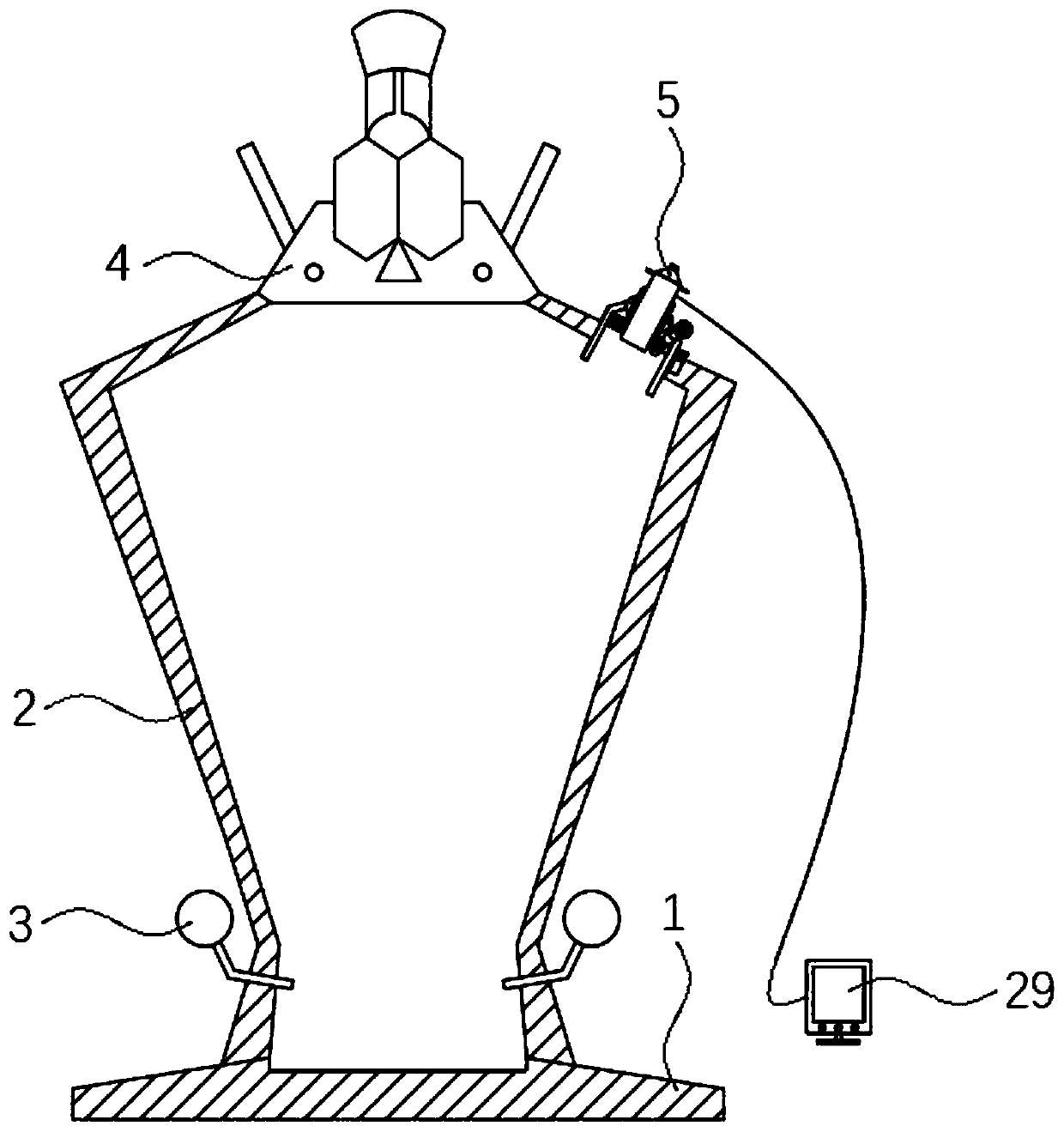
[0028] refer to Figures 1 to 3 , blast furnace roof online night vision thermal imaging diagnostic system, including base 1, furnace body 2, hot air pipe 3 and furnace roof 4, base 1 is fixedly connected to furnace body 2, and hot air pipe 3 is installed on furnace body 2 in the circumferential direction The furnace roof 4 is fixedly connected to the top of the furnace shaft 2 , and the thermal imaging monitoring device 5 is arranged on the side of the furnace shaft 2 close to the furnace roof 4 .

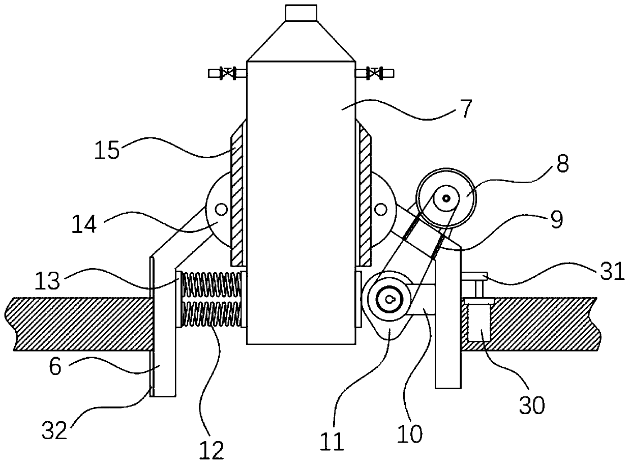
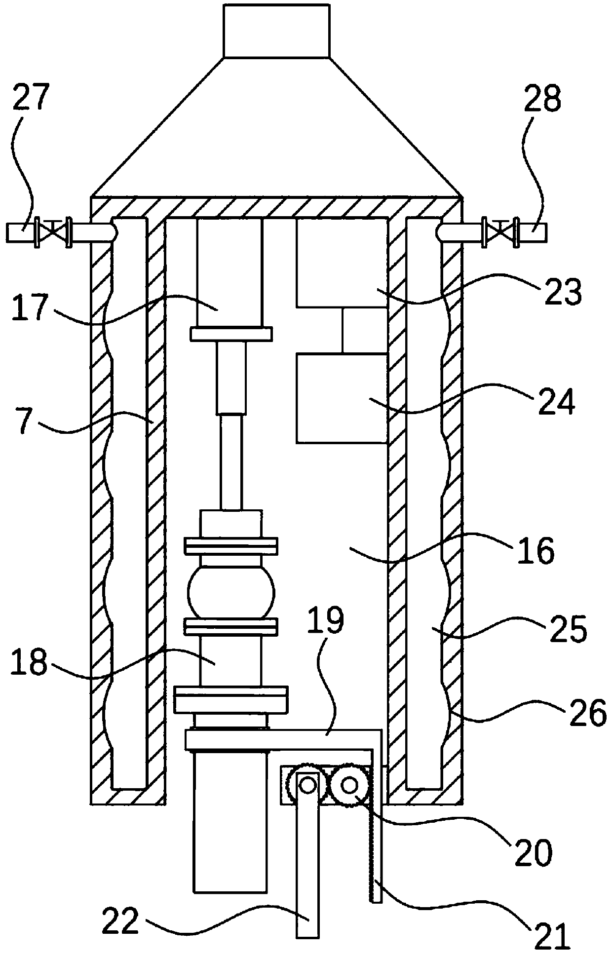
[0029] Thermal imaging monitoring device 5 comprises industrial computer 23, monitoring device 24, display screen 29, thermal imaging device 18, inner sleeve 7 and outer...


PUM


Abstract

The invention discloses an online night-vision thermal imaging diagnosis system for a furnace top of a blast furnace. The online night-vision thermal imaging diagnosis system comprises a base, a furnace body, hot air tubes and the furnace top, wherein the base is fixedly connected with the furnace body; the hot air tubes are circumferentially mounted on the furnace body; the furnace top is fixedlyconnected to the top end of the furnace body; a thermal imaging monitoring device is arranged on the side, close to the furnace top, of the furnace body, and comprises an industrial personal computer, a monitoring device, a thermal camera device, an inner sleeve and an outer sleeve; both the monitoring device and the thermal camera device are electrically connected with the industrial personal computer; and a cavity is formed in the inner sleeve. By the adoption of the online night-vision thermal imaging diagnosis system disclosed by the invention, the high-definition night vision of a material surface and chutes can be achieved through the thermal camera device; the airflow distribution can be clearly visible; the high-definition video images of the material surface and part of the chutes can be displayed in real time with or without visible light; the shapes of part of the chutes, the lining abrasion situation, the motion state, the blanking situation and a mechanical stock rod canbe clearly visible; the gas flow of the material surface within a vision field can be clearly visible; the material surface and the chutes can be subjected to online temperature measurement; and the airflow distribution can be accurately acquired.

Description

technical field [0001] The invention relates to the technical field of blast furnace monitoring devices, in particular to an online night vision thermal imaging diagnosis system for a blast furnace top. Background technique [0002] The blast furnace uses steel plates as the furnace shell, and the shell is lined with refractory bricks. It is a closed and huge high-temperature reaction vessel. 1. The wear condition is of great significance to the operation of the blast furnace, which can directly reflect the production status of the blast furnace. Adjusting the cloth according to the material surface temperature and gas flow distribution can improve the production status of the blast furnace. When the cooling water and cooling gas are abnormal, they cannot be detected and affect the normal production of the blast furnace. [0003] However, although patent No. CN 206188835 U has appeared in the traditional technology, a thermal imaging device for the top of a blast furnace is ...

Claims


Application Information

Patent Timeline
Patent Type & Authority Patents(China)
IPC IPC(8): C21B7/24
CPCC21B7/24
Inventor 金勇
Owner 青岛众志测控技术有限公司
Why Eureka
Try Eureka