


Quick Research
Generate reliable direction feasibility study reports for your R&D in just a few steps.

Technical Q&A
Discover and master advanced knowledge NOW. Basics, ideas, possibilities, all at once.

Find Solutions
As an expert in R&D theories, this can generate solutions to your technical problems instantly.

Evaluate Feasibility
Analyze your overall solution with one click, know your potential R&D risks in advance.

Monitor Landscape
Get weekly tech updates, stay abreast of the latest tech innovations and key insights.
Dust collection cavity and dust collection cleaning equipment
A technology for cleaning equipment and vacuum chambers, which is applied to cleaning equipment, vacuum cleaners, cleaning filter devices, etc. It can solve the problems of not being easy to clean, the gap between the filter screens cannot be too small, and the host is easy to be damaged, so as to achieve convenient and fast cleaning work , Convenient and reliable realization, easy to clean operation effect
- Summary
- Abstract
- Description
- Claims
- Application Information
AI Technical Summary
Problems solved by technology
Method used
Image

Examples
Embodiment 1
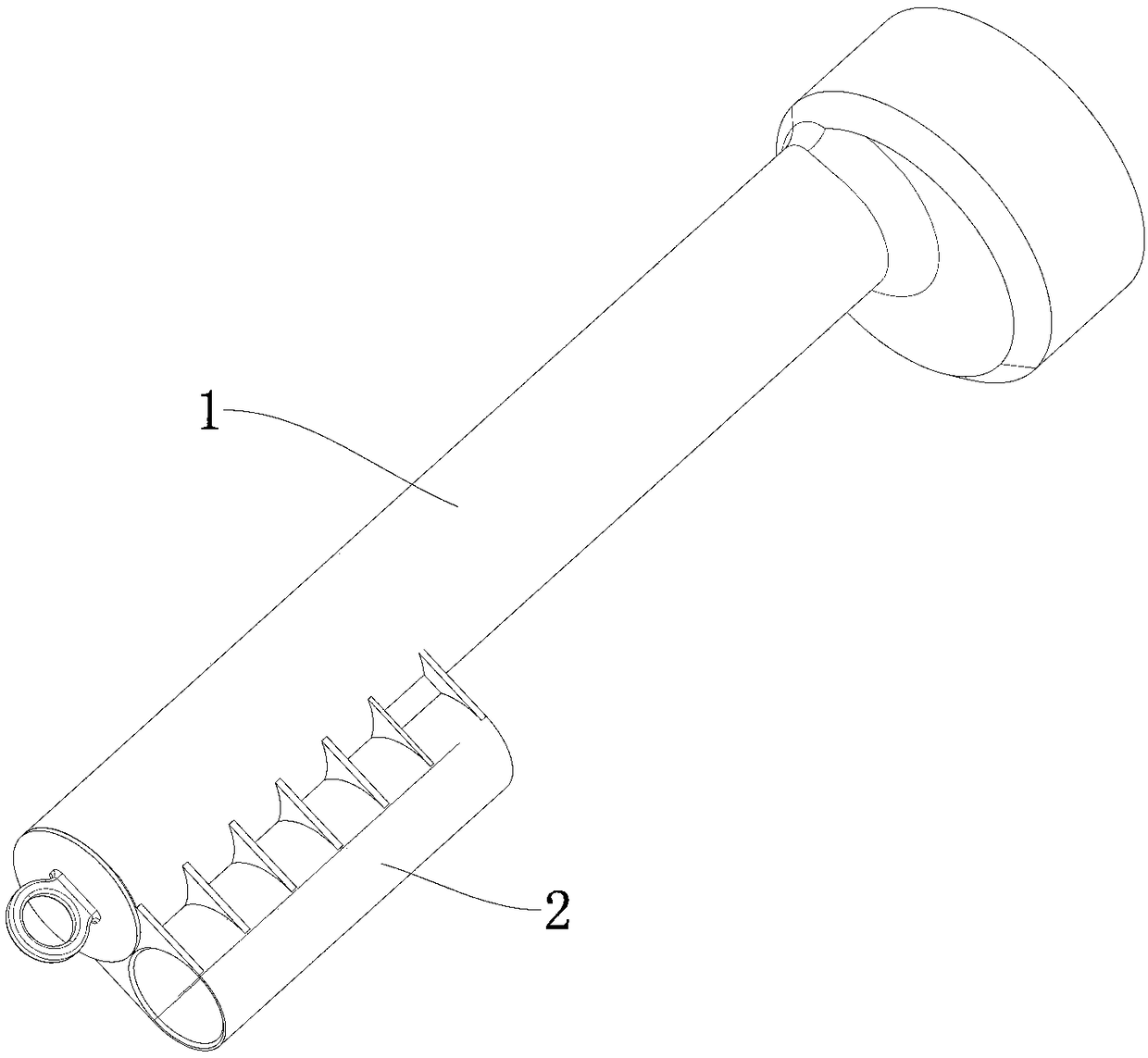
[0028] refer to Figures 1 to 3 , and combined with Image 6 As shown in , the dust suction chamber provided in this embodiment is applied to dust suction cleaning equipment, and the front and rear ends of the dust suction chamber are provided with dust inlets and The dust outlet, and in the direction from the dust inlet to the dust outlet, a wool assembly for absorbing fluff, impurities and some fine dust and a filter cotton 6 for absorbing fine dust are sequentially arranged inside the dust suction chamber.
[0029] Based on the above technical solution, the dust suction chamber is applied to the dust suction cleaning equipment, and the wool assembly and the filter cotton 6 are arranged in the dust suction chamber, so that the fluff, dust and impurities sucked into the dust suction chamber can reside on the wool. On the silk assembly and the filter cotton 6, the cleaning work of the vacuum cleaning equipment can be carried out conveniently and quickly, which is convenient, ...
Embodiment 2
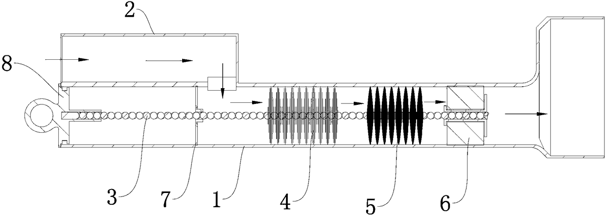
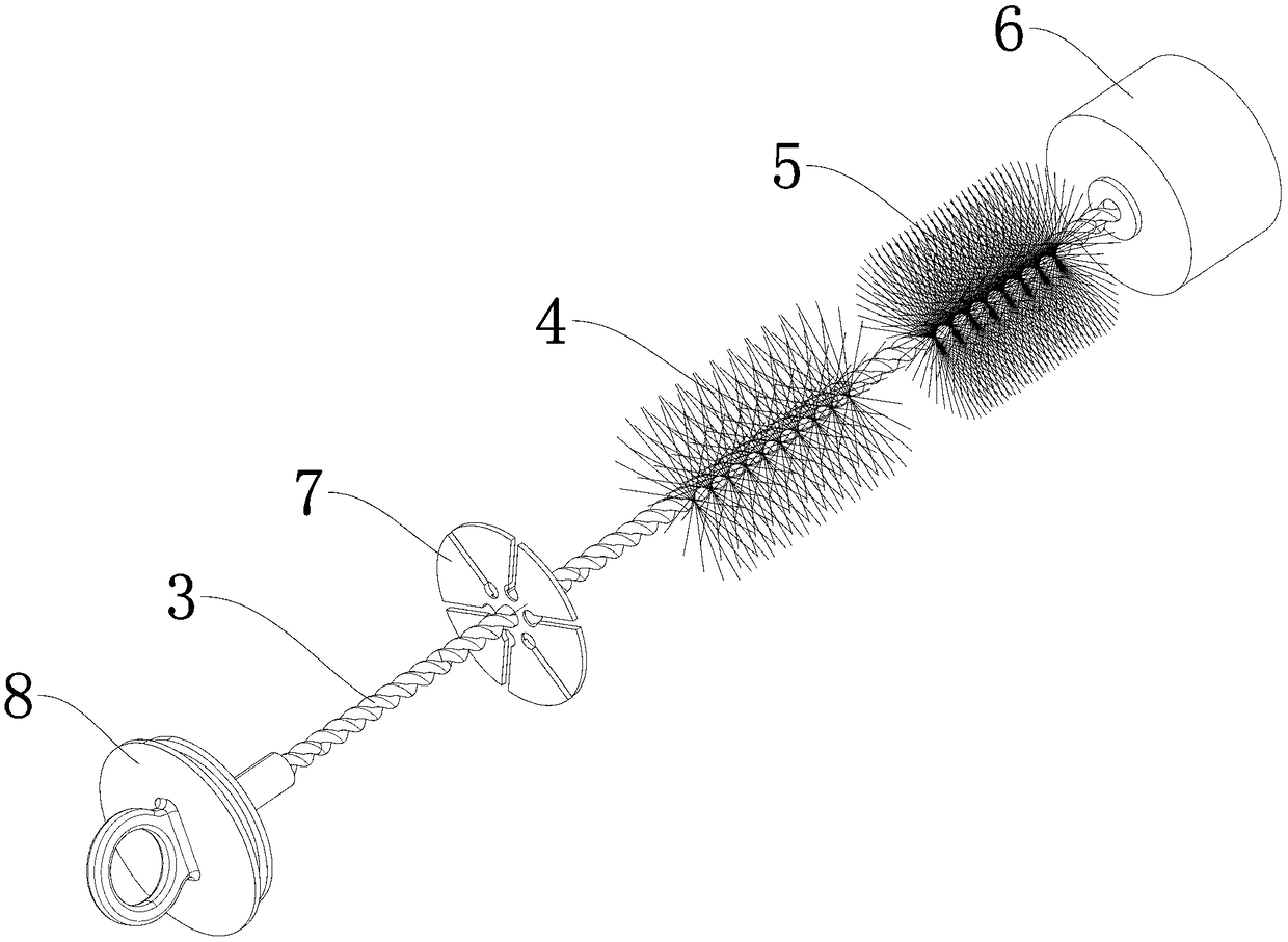
[0034] refer to Figure 4 with Figure 5 As shown in , the overall mechanism and features of the dust suction chamber provided by this embodiment are basically the same as those of the first embodiment above, the only difference is that in this embodiment, the dust suction chamber includes a main pipe 1, and the front end of the main pipe 1 serves as The dust inlet and the rear end are used as the dust outlet, and a connecting bracket 9 is detachably installed inside the main pipe 1 close to the dust outlet. Shaped structure with a number of through holes or a spoke-shaped structure as a whole, so that the dust cleaning mechanism can be drawn out from the dust outlet. Moreover, the detachable installation method of the connecting bracket 9 is basically the same as the installation method of the end cover 8 in the first embodiment above, so details are omitted here. Further, a hand ring is provided on the side of the connecting bracket 9 facing away from the installation rod ...
Embodiment 3
[0036] Such as Image 6 with Figure 7 As shown in , the dust suction cleaning equipment provided in this embodiment includes a host 10, a brush head mechanism 11 and a dust suction cavity as provided in the first embodiment above, and the host 10 is connected to the dust outlet of the dust suction cavity, and the brush head mechanism 11 It is detachably connected to the dust inlet of the dust suction chamber. In addition, the brush head mechanism 11 can be various types of dust-absorbing brush heads such as a ground brush assembly, a roller brush assembly, or even a mechanical brush head without an electric mechanism, but is not limited thereto.
PUM
 Abstract
Description
Claims
Application Information
 - R&D Engineer
- R&D Manager
- IP Professional
- Industry Leading Data Capabilities
- Powerful AI technology
- Patent DNA Extraction
Browse by: Latest US Patents, China's latest patents, Technical Efficacy Thesaurus, Application Domain, Technology Topic, Popular Technical Reports.
© 2024 PatSnap. All rights reserved.Legal|Privacy policy|Modern Slavery Act Transparency Statement|Sitemap|About US| Contact US: help@patsnap.com