
Rotary overhead wire spreader

A kind of overhead wire, rotary technology, applied in the direction of overhead line/cable equipment, etc., can solve the problems of inconvenient operation, hidden safety hazards, hidden dangers, etc., and achieve the effect of convenient operation

Active Publication Date: 2020-03-24
STATE GRID ZHEJIANG ELECTRIC POWER CO LTD QUZHOU POWER SUPPLY CO +1
View PDF4 Cites 0 Cited by
  • Summary
  • Abstract
  • Description
  • Claims
  • Application Information

AI Technical Summary

Problems solved by technology

[0003] First, use two electrified trolleys to carry out operations, and the electrified trolley stops at the two wires, and the construction personnel pull the conductors apart through the electrified trolley. This operation method requires the cooperation of the electrified trolley and some construction personnel, and the operation is inconvenient;
[0004] Its two, tie the insulating working rope on the two wires, and two construction workers pull the wires apart on the ground. This operation method pulls the overhead wires apart by manpower, and there is a big potential safety hazard.
[0005] Third, after the two wires are pulled apart, they are respectively connected to the insulating rod through the binding rope, so that the two wires are stretched apart. The connection between the binding rope and the support rod often requires several personnel to work together to stretch and position the wires. , and there is a greater security risk

Method used


Image

  • Rotary overhead wire spreader
  • Rotary overhead wire spreader
  • Rotary overhead wire spreader

Examples


specific Embodiment 1

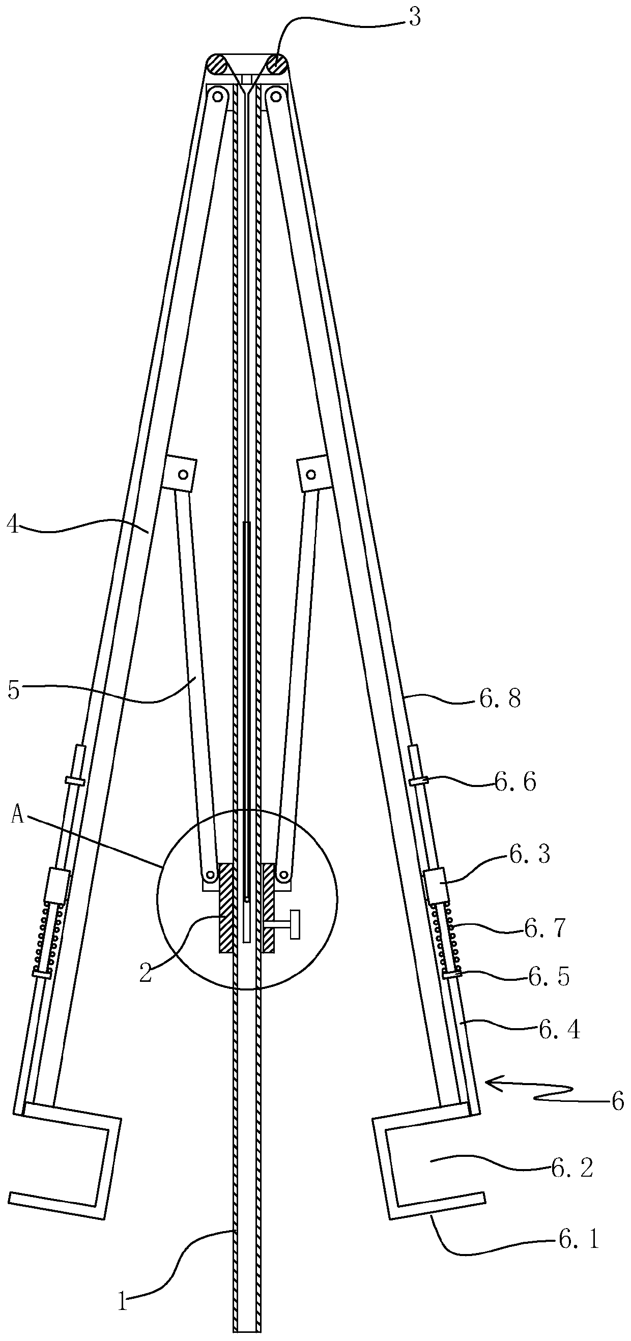
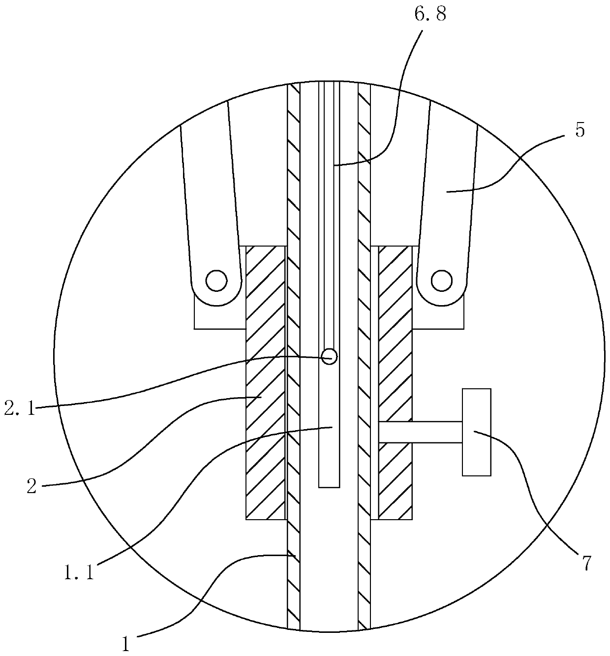
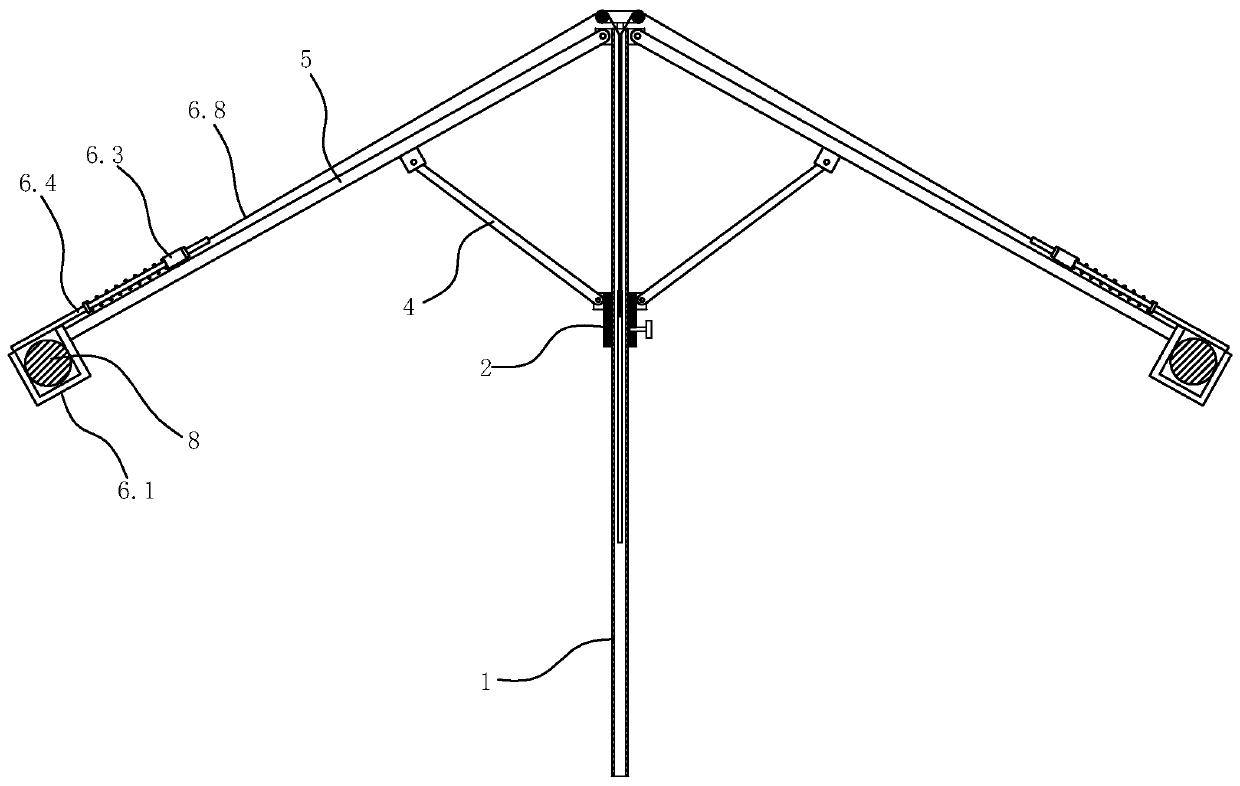
[0035] Specific embodiment one: such as figure 1 , figure 2 As shown, a rotating overhead wire spreading device includes a vertical riser 1, a strip hole 1.1 arranged on the wall of the vertical riser and extending along the axial direction of the vertical riser, and a connecting piece and The guide ring 3 connected to the vertical riser and located above the vertical riser, the sliding sleeve that slides along the vertical riser 2, the sliding sleeve locking bolt 7 arranged on the sliding sleeve, and the inner side surface of the sliding sleeve The tie rod 2.1, two struts 4 distributed on opposite sides of the vertical riser, and one-to-one corresponding adaptive wire fixing device 6 arranged on the struts.

[0036] The upper and lower ends of the vertical riser are open. The guide ring is coaxial with the vertical riser. The material of the vertical riser is insulating material, such as plastic material.

[0037] Two support rods are symmetrically distributed on opposite side...


PUM


Abstract

The invention discloses a rotary overhead conductor opening device, and aims to provide the rotary overhead conductor opening device which can open two overhead conductors reliably, provides a sufficient operation space for vertical rod operation, and is convenient to operate. The device comprises a vertical pipe, a strip-shaped hole formed in the pipe wall of the vertical pipe and extending in anaxial direction of the vertical pipe, guide rings connected with the vertical pipe through connecting pieces and positioned above the vertical pipe, a sliding sleeve which slides along the vertical pipe, a sliding sleeve locking bolt arranged on the sliding sleeve, a pull rod arranged on the inner side surface of the sliding sleeve, two supporting rods distributed on the two opposite sides of thevertical pipe, and self-adaptive wire fixing devices arranged on the supporting rods in a one-to-one correspondence mode. The upper ends of the supporting rods are hinged to the upper end of the vertical pipe; the supporting rods are connected with the sliding sleeve through connecting rods; and one end of each connecting rod is hinged to the middle of each supporting rod, and the other end of each connecting rod is hinged to the sliding sleeve.

Description

Technical field [0001] The invention relates to a power construction appliance, in particular to a rotating overhead wire spreading device. Background technique [0002] At present, when a new high-voltage electric pole needs to be erected on a certain section of the high-voltage line, the two parallel wires need to be pulled apart to increase the distance between the wires, so as to provide enough working space for the pole operation to ensure the operation Safety. At present, there are several ways to open the two wires: [0003] One is to use two trams for work. The trams are parked at the two wires, and the construction workers pull the wires apart through the trams. This operation requires the cooperation of trams and a number of construction workers, which is inconvenient to operate; [0004] Secondly, two conductors are tied with insulating work ropes, and two construction workers pull the conductors apart on the ground. This operation method uses humans to pull the overhead...

Claims


Application Information

Patent Timeline
Patent Type & Authority Patents(China)
IPC IPC(8): H02G1/02
CPCH02G1/02
Inventor 黄宏和许屹华晓周光乐严伟雄黄炎阶杨谦杨永峰周治国俞伟杰张晓郑樟磊曾君军王浩
Owner STATE GRID ZHEJIANG ELECTRIC POWER CO LTD QUZHOU POWER SUPPLY CO
Learn More