
Amplification output method and system for optical signal

An output method, output system technology

Inactive Publication Date: 2019-03-12
O NET COMM (SHENZHEN) LTD
View PDF4 Cites 4 Cited by
  • Summary
  • Abstract
  • Description
  • Claims
  • Application Information

AI Technical Summary

Problems solved by technology

[0006] The technical problem to be solved by the present invention is to provide a method and system for amplifying and outputting an optical signal to solve the problem that the optical signal cannot be amplified when the target output power of the laser is small.

Method used


Image

  • Amplification output method and system for optical signal
  • Amplification output method and system for optical signal
  • Amplification output method and system for optical signal

Examples


Embodiment Construction

[0025] Now in conjunction with the accompanying drawings, the preferred embodiments of the present invention will be described in detail.

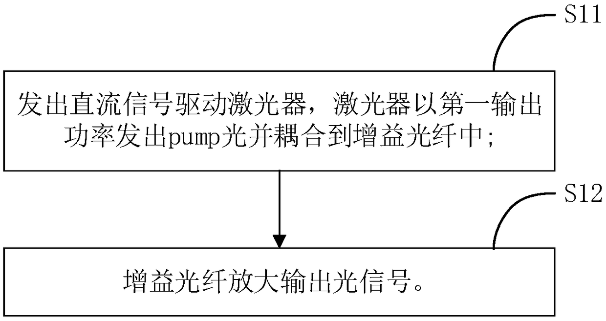
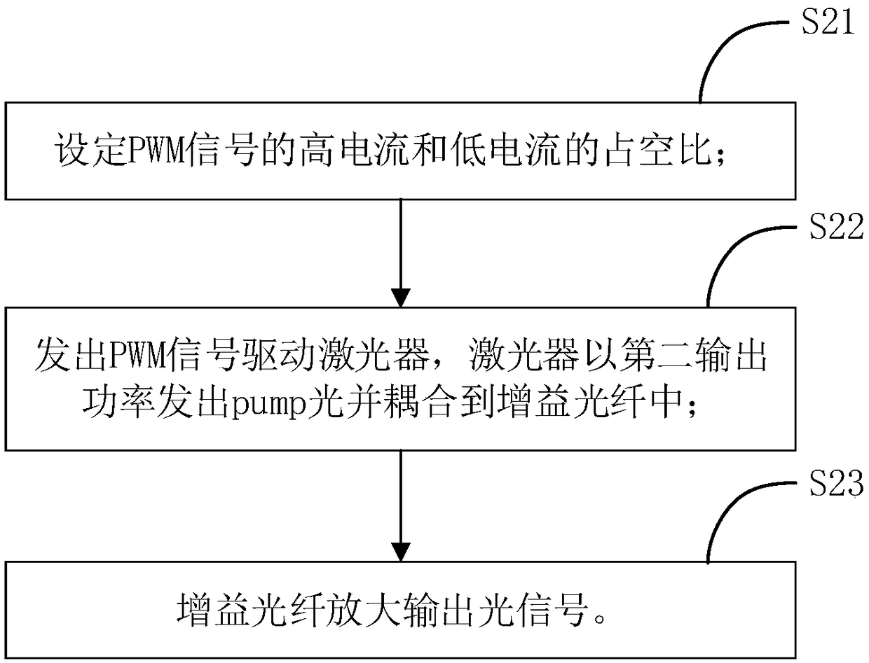
[0026] Such as Figure 1 to Figure 3 As shown, the present invention provides a preferred embodiment of a method for amplifying and outputting an optical signal.

[0027] Specifically, a method for amplifying and outputting an optical signal, wherein the amplifying and outputting method adopts different methods for amplifying and outputting an optical signal for the following two different situations.

[0028] Situation 1. Reference figure 1 , when the required output optical signal matches the laser drive current and the laser threshold current have a first relationship, the amplifying output method includes the following steps:

[0029] Step 11, send a DC signal to drive the laser, and the laser sends pump light with the first output power and couples it into the gain fiber;

[0030] Step 12, the gain fiber amplifies and outputs the o...


PUM


Abstract

The invention relates to an amplification output method and system for an optical signal. The amplification output method comprises the following steps that: when laser driving current matched with arequired output optical signal and laser threshold value current are in a first relationship, a direct current signal is emitted to drive a laser, the laser emits pump light by first output power, thepump light is coupled to a gain optical fiber, and the gain optical fiber amplifies the output optical signal; and when the laser driving current matched with the required output optical signal and the laser threshold value current are in a second relationship, the duty cycle of the high current and the low current of a PWM (Pulse-Width Modulation) signal is set, the PWM signal is emitted to drive the laser, the laser emits pump light by second output power, the pump light is coupled to the gain optical fiber, and the gain optical fiber amplifies the output optical signal. No matter whether the target power required by the laser is large or small, the optical signal can be kept stable, and a gain effect is guaranteed.

Description

technical field [0001] The invention relates to the field of optical amplification, in particular to an optical signal amplification and output method and system. Background technique [0002] Erbium-doped fiber amplifier (EDFA) is an indispensable amplification unit for optical fiber communication links. In the design and application, it is necessary to comprehensively consider various optical indicators such as input and output power, power stability, gain range, and noise requirements. To adapt to different application environments. [0003] A typical application scenario is that moderate optical signal gain is required at low input power, and the final output power of the amplifier will not be very large at this time. EDFA uses the pump light to generate stimulated radiation in the erbium-doped fiber, and transfers the energy to the signal light, so as to achieve the purpose of amplifying the specific signal light. By increasing or decreasing the pump light power, it ca...

Claims


Application Information

Patent Timeline
IPC IPC(8): H01S3/067
CPCH01S3/06716H01S3/0675H01S3/06754
Inventor 熊奇
Owner O NET COMM (SHENZHEN) LTD
Learn More