
Heat dissipation structure and heat dissipation method of a pcr detector

A heat dissipation structure and detector technology, applied in the field of PCR amplification, to achieve the effect of extending equipment, ensuring accuracy, and stable optical signals

Active Publication Date: 2022-05-24
INTEGRATED BIOSYSTEMS CO LTD
View PDF5 Cites 0 Cited by
  • Summary
  • Abstract
  • Description
  • Claims
  • Application Information

AI Technical Summary

Problems solved by technology

This device is used to enhance the heat dissipation effect, but the air box is used to ventilate the main body of the PCR instrument, which still cannot avoid the influence of the optical path after the air is heated during the detection process

Method used


Image

  • Heat dissipation structure and heat dissipation method of a pcr detector
  • Heat dissipation structure and heat dissipation method of a pcr detector
  • Heat dissipation structure and heat dissipation method of a pcr detector

Examples


Embodiment

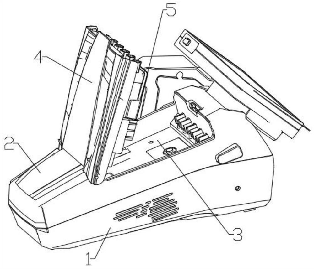
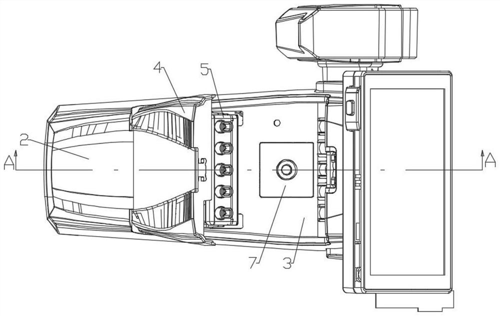
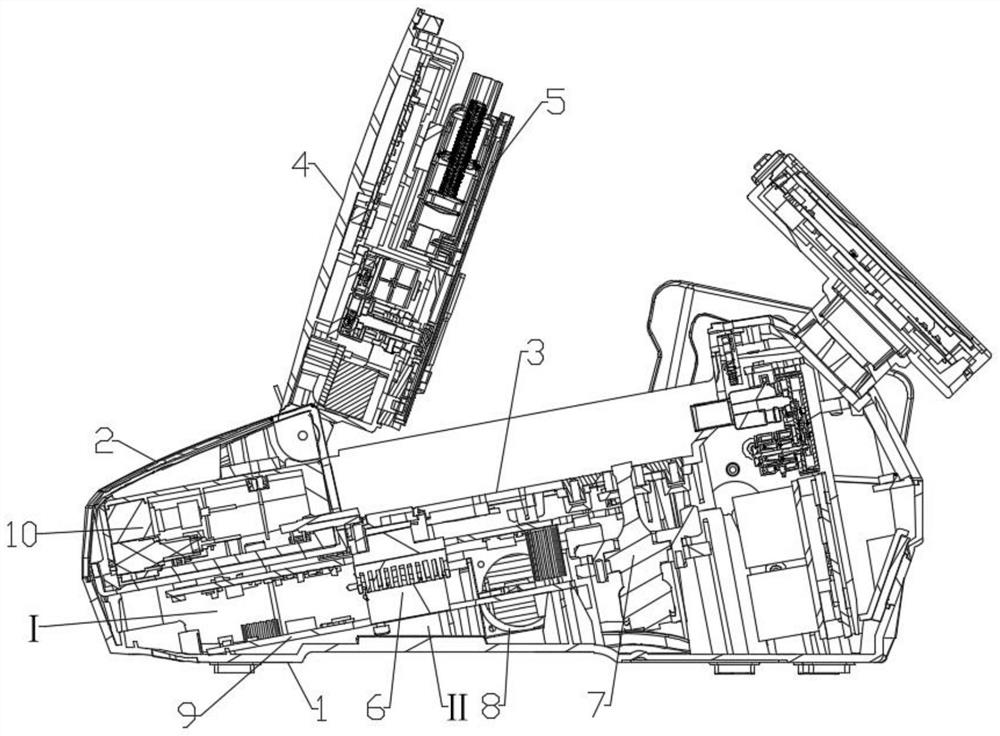
[0041] combine Figure 1-5 As shown, this embodiment discloses a heat dissipation structure of a PCR detector, which includes a lower case 1 and a detection case 2, the lower case 1 and the detection case 2 are fixed by a buckle connection, and the lower case 1 It forms a hollow cavity structure with the detection housing 2, see Figure 4-5 As shown, the lower case 1 includes a first side 102, a second side 103, a third side 104, a fourth side 105 and a first bottom 101, the first bottom 101 is placed on the ground horizontally, and the first bottom 101 The width of one end is smaller than the width of the opposite end, and the four corners of the lower surface of the first bottom surface 101 are provided with support installation grooves 107, and a support body is fixedly connected in the support installation groove 107; the first side surface 102 is fixedly connected to the upper width of the first bottom surface 101 The smaller end, the second side 103 is fixedly connected...


PUM


Abstract

The invention relates to a heat dissipation structure of a PCR detector, comprising a lower case and a detection case, the lower case and the detection case are fixed by a buckle connection, and the lower case and the detection case form a hollow cavity structure In this heat dissipation structure, by setting the structure of the lower shell and combining the design of the installation position of the heat dissipation fan and exhaust fan, while realizing heat dissipation inside the detector, the area of ​​the excitation light mechanism and the area of ​​the air inlet are kept at negative pressure to avoid the return of hot air to the The area of ​​the excitation light mechanism and the position of the air inlet ensure that the light signal of the excitation light mechanism will not be affected by the temperature of other mechanisms in the detector, ensure stable transmission of light signals, and improve the accuracy of detection results.

Description

technical field [0001] The invention relates to the technical field of PCR amplification, in particular to a heat dissipation structure and heat dissipation method of a PCR detector. Background technique [0002] The basic principle of PCR technology is similar to the natural replication process of DNA. Its specificity mainly depends on the oligonucleotide primers complementary to both ends of the target sequence. It consists of three basic reaction steps: denaturation-refolding-extension: Denaturation of DNA: After the template DNA is heated to about 93°C for a certain period of time, the double-stranded DNA of the template DNA or the double-stranded DNA formed by PCR amplification is dissociated to make it single-stranded so that it can be combined with the primer for the next round of reaction Preparation; followed by annealing (annealing) of the template DNA and primers: after the template DNA is heated and denatured into a single strand, the temperature drops to about 5...

Claims


Application Information

Patent Timeline
Patent Type & Authority Patents(China)
IPC IPC(8): H05K7/20C12M1/38
CPCH05K7/20145H05K7/20172H05K7/20209C12M1/38
Inventor 范东雨吴世超王宏伟任玮鹏蒋鹏翀蔡亦梅任鲁风
Owner INTEGRATED BIOSYSTEMS CO LTD
Learn More