A special-shaped cavity three-mode resonant structure and a filter containing the resonant structure

A resonant structure and cavity technology, applied in resonators, waveguide devices, circuits, etc., can solve problems such as installation and debugging of unfavorable dielectric resonant blocks, mass production of unfavorable dielectric resonant blocks, and limited adjustment range of tuning screws, etc., to achieve simple structure , The effect of material cost reduction and volume reduction

Active Publication Date: 2021-04-30
HONGKONG FINGU DEV CO LTD
View PDF6 Cites 0 Cited by
  • Summary
  • Abstract
  • Description
  • Claims
  • Application Information

AI Technical Summary

Problems solved by technology

However, this structure has the following technical problems: 1. Because the distance between the dielectric resonator block and the inner wall of the cavity is extremely small, the adjustment range of the tuning screw is limited, which is not conducive to the installation and debugging of the dielectric resonator block; The distance between the inner walls of the cavity is extremely small, so the distance between the dielectric resonator block and the cavity is highly sensitive to the resonance frequency of the single cavity, which is not conducive to the mass production of the dielectric resonator block; 3. Because the distance between the dielectric resonator block and the inner wall of the cavity The small spacing is highly sensitive to the resonance frequency of a single cavity, so the design accuracy of the dielectric resonator block and the cavity is extremely high, which increases the manufacturing cost

Method used


Image

  • A special-shaped cavity three-mode resonant structure and a filter containing the resonant structure
  • A special-shaped cavity three-mode resonant structure and a filter containing the resonant structure
  • A special-shaped cavity three-mode resonant structure and a filter containing the resonant structure

Examples


Embodiment Construction

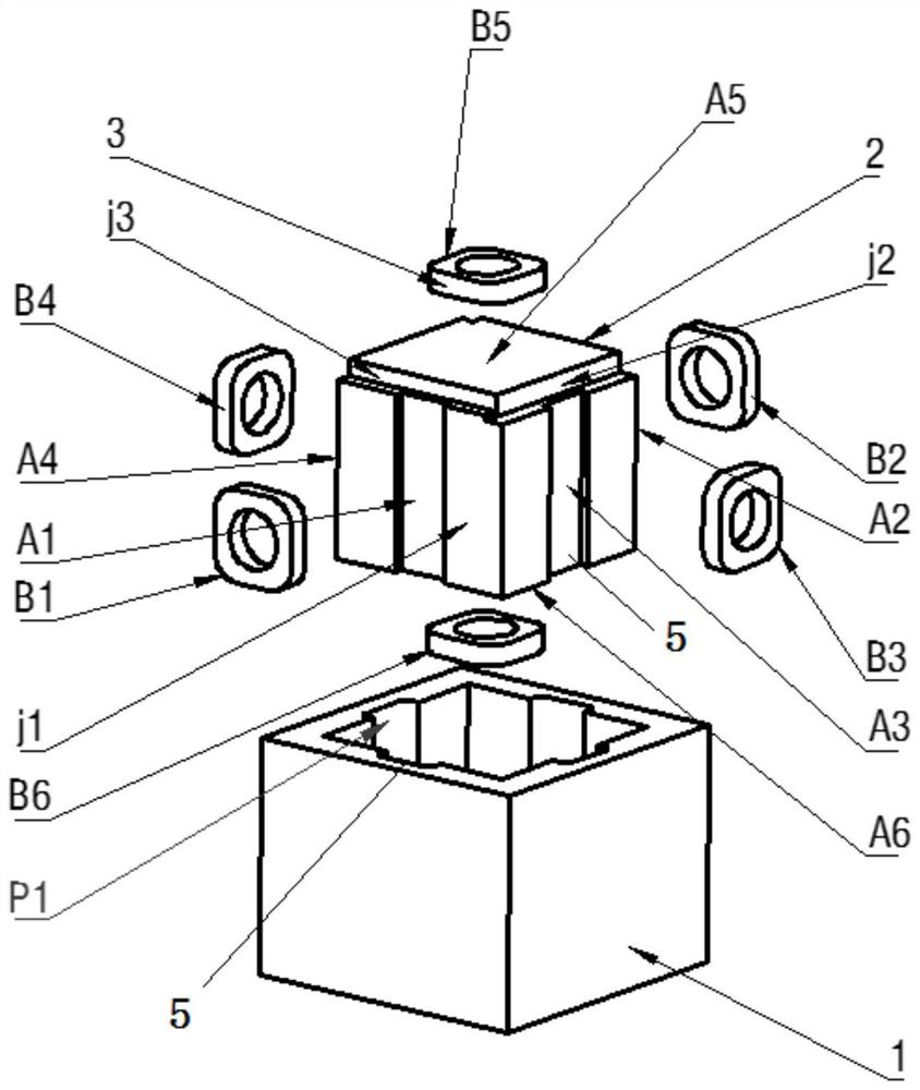
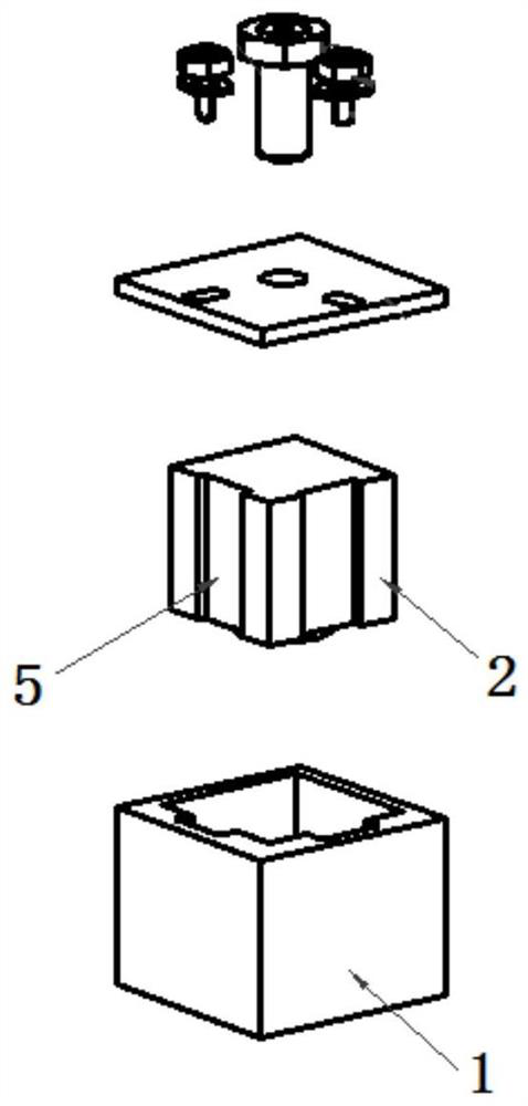
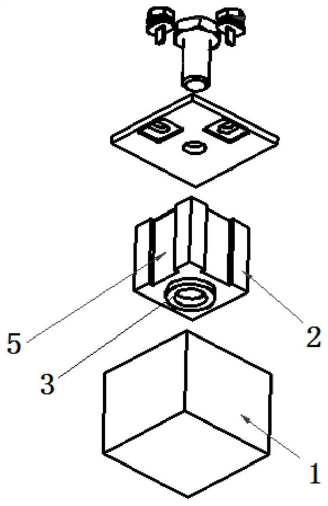
[0057] The invention discloses a special-shaped cavity three-mode resonant structure, which includes a cavity and a cover plate, and a dielectric resonator block and a dielectric support frame are arranged in the cavity, and the feature is that the cavity is similar to a cube shape And at least one end surface is concave, the dielectric resonance block is similar to a cube shape and at least one end surface is convex, the dielectric support frame is respectively connected to the dielectric resonance block and the inner wall of the cavity, and the dielectric resonance block is connected to the The dielectric support frame constitutes a three-mode dielectric resonant rod, and the dielectric constant of the dielectric support frame is smaller than the dielectric constant of the dielectric resonator block; The ratio K between the dimensions of the sides is: when conversion point 1≤K≤transition point 2, the Q value of the higher mode adjacent to the fundamental mode is converted int...


PUM


Abstract

The patent of the present invention discloses a special-shaped cavity multi-mode resonance structure and a filter containing the resonance structure, including a cavity and a cover plate, a dielectric resonance block and a dielectric support frame are arranged in the cavity, and at least one end face of the cavity is Concave or convex, at least one end face of the dielectric resonant block is convex or concave, the dielectric resonant block and the dielectric support frame form a three-mode dielectric resonator rod, one end or any end of the dielectric resonant block similar to a cube is connected to the dielectric support frame respectively, the dielectric The support frame is connected with the inner wall of the cavity, and the dielectric resonance block forms three-mode resonance in the three directions of the X, Y, and Z axes of the cavity. The use of the cavity filter of the present invention can ensure that a high Q value can be obtained with a small distance between the resonant rod and the cavity, and at the same time, the tuning range of the tuning screw is increased, and the small distance between the cavity and the dielectric resonant block is reduced. The sensitivity of the resonance frequency is convenient for production debugging and reduces the production cost.

Description

technical field [0001] The invention relates to base station filters, antenna feeder filters, combiners and anti-interference filters used in the field of wireless communication. The types of filters can be band-pass, band-stop, high-pass and low-pass. A special-shaped cavity three-mode resonant structure and a filter containing the special-shaped cavity three-mode resonant structure. Background technique [0002] With the rapid development of the fourth-generation mobile communication to the fifth-generation mobile communication, the requirements for miniaturization and high performance of communication equipment are getting higher and higher. Traditional filters are gradually replaced by single-mode dielectric filters due to their large metal cavity volume and general performance. Single-mode dielectric filters mainly include TE01-mode dielectric filters and TM-mode dielectric filters, TE01-mode dielectric filters and The TM mode dielectric filter generally adopts a singl...

Claims


Application Information

Patent Timeline
Patent Type & Authority Patents(China)
IPC IPC(8): H01P1/207
CPCH01P1/207H01P7/06H01P7/105H01P1/2086
Inventor 孟庆南
Owner HONGKONG FINGU DEV CO LTD
Why Eureka
Try Eureka