Special-shaped cavity tri-mode resonant structure and filter containing the same

A resonant structure and cavity technology, applied in the field of filters, can solve the problems of limited adjustment range of tuning screw, high sensitivity of single cavity resonant frequency, and unfavorable mass production of dielectric resonant blocks.

Active Publication Date: 2019-03-12
HONGKONG FINGU DEV CO LTD
View PDF6 Cites 4 Cited by
  • Summary
  • Abstract
  • Description
  • Claims
  • Application Information

AI Technical Summary

Problems solved by technology

However, this structure has the following technical problems: 1. Because the distance between the dielectric resonator block and the inner wall of the cavity is extremely small, the adjustment range of the tuning screw is limited, which is not conducive to the installation and debugging of the dielectric resonator block; The distance between the inner walls of the cavity is extremely small, so the distance between the dielectric resonator block and the cavity is highly sensitive to the resonance frequency of the single cavity, which is not conducive to the mass production of the dielectric resonator block; 3. Because the distance between the dielectric resonator block and the inner wall of the cavity The small spacing is highly sensitive to the resonance frequency of a single cavity, so the design accuracy of the dielectric resonator block and the cavity is extremely high, which increases the manufacturing cost

Method used


Image

  • Special-shaped cavity tri-mode resonant structure and filter containing the same
  • Special-shaped cavity tri-mode resonant structure and filter containing the same
  • Special-shaped cavity tri-mode resonant structure and filter containing the same

Examples


Embodiment Construction

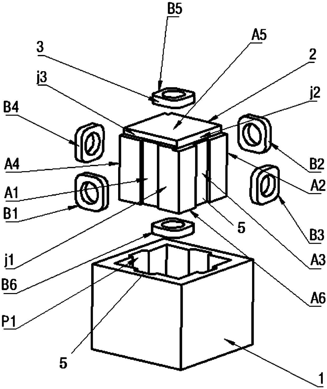
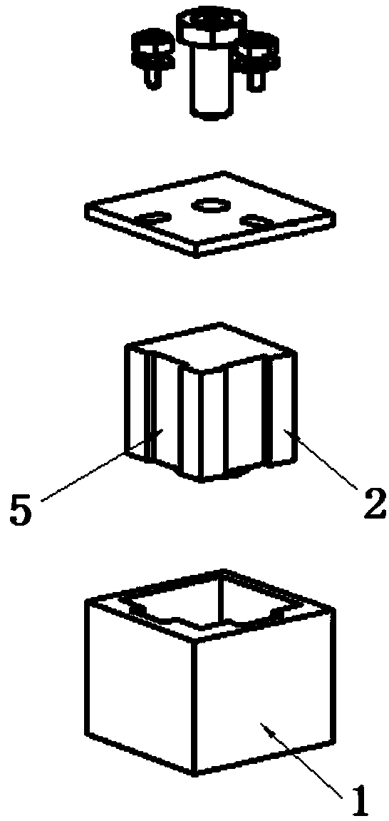
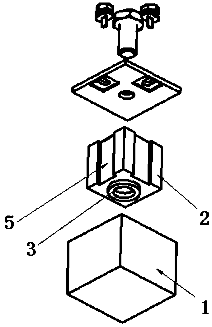
[0057] The special-shaped cavity multimode resonant structure described in the following embodiments includes:

[0058] The cavity is a special-shaped concave, while the dielectric resonance block is a special-shaped convex, and the dielectric support frame;

[0059] The cavity is a special-shaped convex, while the dielectric resonance block is a special-shaped concave, and the dielectric support frame;

[0060] The medium support frame is made to match the special-shaped structure, and the number can be one or more. The shape can be a regular shape, such as a solid / hollow cylinder, a solid / hollow square column, etc., or an irregular shape; or it can be composed of multiple columns.

[0061] In order to ensure multi-mode and corresponding frequency, the special-shaped structure cannot be infinitely concave or convex, and there are certain restrictions. An example is given below to illustrate, and others can be obtained similarly.

[0062] Eg: Single cavity 26mm×26mm×26mm, d...


PUM


Abstract

The patent for invention discloses a special-shaped cavity tri-mode resonant structure and a filter containing the same. The special-shaped cavity tri-mode resonant structure comprises a cavity and acover plate. A medium resonant block and a medium support frame are arranged in the cavity; at least one end surface of the cavity is concave or convex, and at least one end surface of the medium resonant block is convex or concave; the medium resonant block and the medium support frame form a tri-mode medium resonant rod; one end or any end of a similar cubic medium resonant block is respectivelyconnected with the medium support frame; the medium support frame is connected with the inner wall of the cavity; and the medium resonant block forms tri-mode resonance in three directions of an X axis, a Y axis and a Z axis of the cavity. The cavity filter in the invention is used so that a high Q value is ensured to be obtained under a small distance between the resonant rod and the cavity; meanwhile, the tuning range of a tuning screw rod is enlarged, the sensitiveness of the small distance between the cavity and the medium resonant block to the resonant frequency is reduced, production and debugging are facilitated, and the production cost is reduced.

Description

technical field [0001] The invention relates to base station filters, antenna feeder filters, combiners and anti-interference filters used in the field of wireless communication. The types of filters can be band-pass, band-stop, high-pass and low-pass. A special-shaped cavity three-mode resonant structure and a filter containing the special-shaped cavity three-mode resonant structure. Background technique [0002] With the rapid development of the fourth-generation mobile communication to the fifth-generation mobile communication, the requirements for miniaturization and high performance of communication equipment are getting higher and higher. Traditional filters are gradually replaced by single-mode dielectric filters due to their large metal cavity and general performance. Single-mode dielectric filters mainly include TE01-mode dielectric filters and TM-mode dielectric filters, TE01-mode dielectric filters and TM-mode dielectric filters. Mode dielectric filters generally...

Claims


Application Information

Patent Timeline
IPC IPC(8): H01P1/207
CPCH01P1/207H01P7/06H01P7/105H01P1/2086
Inventor 孟庆南
Owner HONGKONG FINGU DEV CO LTD
Why Eureka
Try Eureka