An excitation layout optimization method for improving plasma excitation flow control efficiency

A plasma and flow control technology, applied in the field of plasma, can solve the problems that flow control measures are difficult to be applied in practical engineering and difficult to effectively suppress.

Active Publication Date: 2019-03-12
AIR FORCE UNIV PLA
View PDF3 Cites 2 Cited by
  • Summary
  • Abstract
  • Description
  • Claims
  • Application Information

AI Technical Summary

Problems solved by technology

The three-dimensional corner separation originates from the secondary flow and reverse pressure gradient in the blade channel, and is directly related to the load level of the blade. Therefore, it is difficult to effectively suppress it under the condition of high-speed incoming flow with the existing plasma excitation intensity. Therefore, the high-speed compressor Three-dimensional corner-separated plasma flow control requires a more efficient excitation layout
The formation mechanism of three-dimensional corner separation determines that the suppression of three-dimensional corner separation of high-speed compressors must require higher excitation intensity, and flow control measures with high power consumption are difficult to apply to practical engineering

Method used


Image

  • An excitation layout optimization method for improving plasma excitation flow control efficiency
  • An excitation layout optimization method for improving plasma excitation flow control efficiency
  • An excitation layout optimization method for improving plasma excitation flow control efficiency

Examples


Embodiment Construction

[0049] The specific implementation of the present invention will be further described below in conjunction with the accompanying drawings.

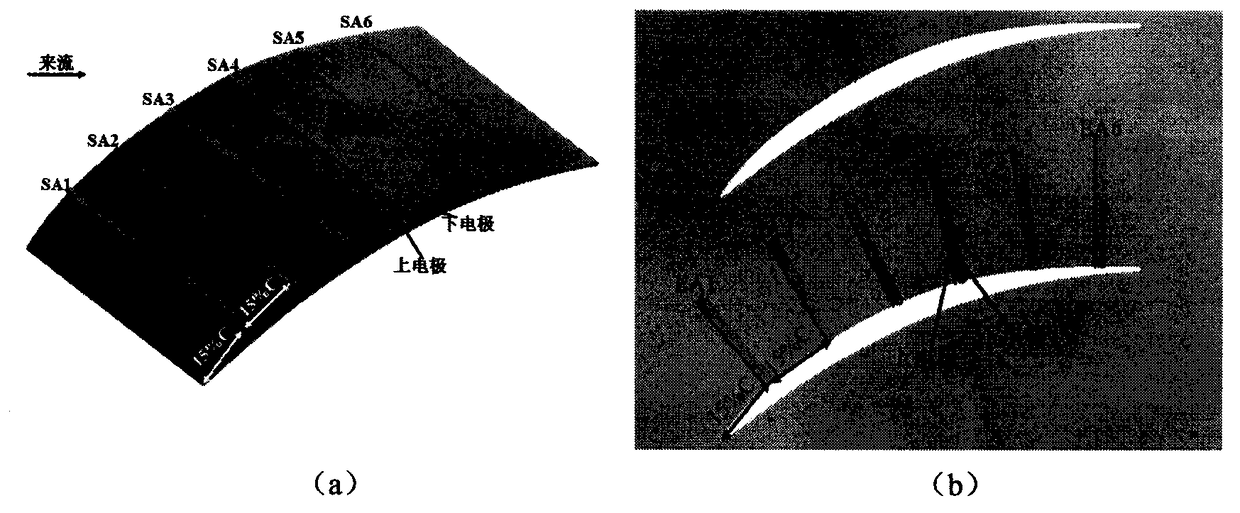
[0050] The present invention is developed for a high-speed compressor cascade model. The high-speed compressor cascade model is NACA65-K48 high-speed compressor cascade, and its main aerodynamic parameters are shown in the table below. The numerical simulation calculation adopts Ansys CFX commercial fluid software, and uses the RANS method to carry out unsteady numerical simulation. The grid topology in the numerical simulation method is H-O-H. In order to more accurately simulate the influence of plasma excitation on the flow field of the high-speed compressor cascade, the numerical simulation grid is figure 1 The position of the plasma exciter in the center is locally refined, and the final total number of grids is 2.8 million. The selected turbulence model is still the k-ω eddy viscosity model. The body force induced by plasma excit...


PUM


Abstract

A method for optimize a plasma excitation layout is disclosed. That plasma excitation is arranged into a suction surface excitation layout, an end wall excitation layout and a combined excitation layout. The benefits of plasma-excited flow control effects relative to the combined excitation distribution are calculated respectively. The larger the plasma-excited flow control effect is, the better the plasma-excited flow control effect is. The parameter Opg is defined to evaluate the energy consumption and flow control benefits of each plasma excitation comprehensively. The combination of plasmaexcitation with high efficiency of flow control is selected and applied to the cascade channel to obtain the optimized plasma excitation layout. The invention selects the combined excitation layout of the suction surface and the end wall as a reference, By considering the energy consumption and flow control benefit of the plasma excitations arranged on the suction surface and the end wall of theblade, the flow control efficiency of the plasma excitations is evaluated, and the optimized excitation layout is obtained to realize the efficient control of the flow separation in the high speed compressor cascade.

Description

technical field [0001] The invention relates to plasma technology, in particular to an excitation layout optimization method for improving plasma excitation flow control efficiency. Background technique [0002] The corner area generally refers to the junction of the compressor blades and the casing / hub. The three-dimensional angular area separation starting from the root of the rotor and the proximal end of the stator is an important source of compressor flow loss, which will cause strong flow blockage and large The lagging angle of the airflow limits the increase of the compressor load. The passive flow control method has a strong influence on the three-dimensional angular separation of the compressor. The three-dimensional angular separation can be significantly weakened within the specified working range through a reasonable design of the flow control scheme. However, the passive control method usually causes The redistribution of low-energy fluid or fluid momentum will...

Claims


Application Information

Patent Timeline
IPC IPC(8): G06F17/50
CPCG06F30/367
Inventor 张海灯吴云李应红宋慧敏
Owner AIR FORCE UNIV PLA
Why Eureka
Try Eureka