Axial dual-direction positioning and stretching hollow blow molding method
A technology of positioning stretching and blow molding, which is applied in the field of blow molding container molding, can solve problems such as stress concentration, insufficient rigidity, and unstable speed of the stretching rod, and achieve the effect of enhancing the overall strength and uniform wall thickness
- Summary
- Abstract
- Description
- Claims
- Application Information
AI Technical Summary
Problems solved by technology
Method used
Image
Examples
Embodiment 1
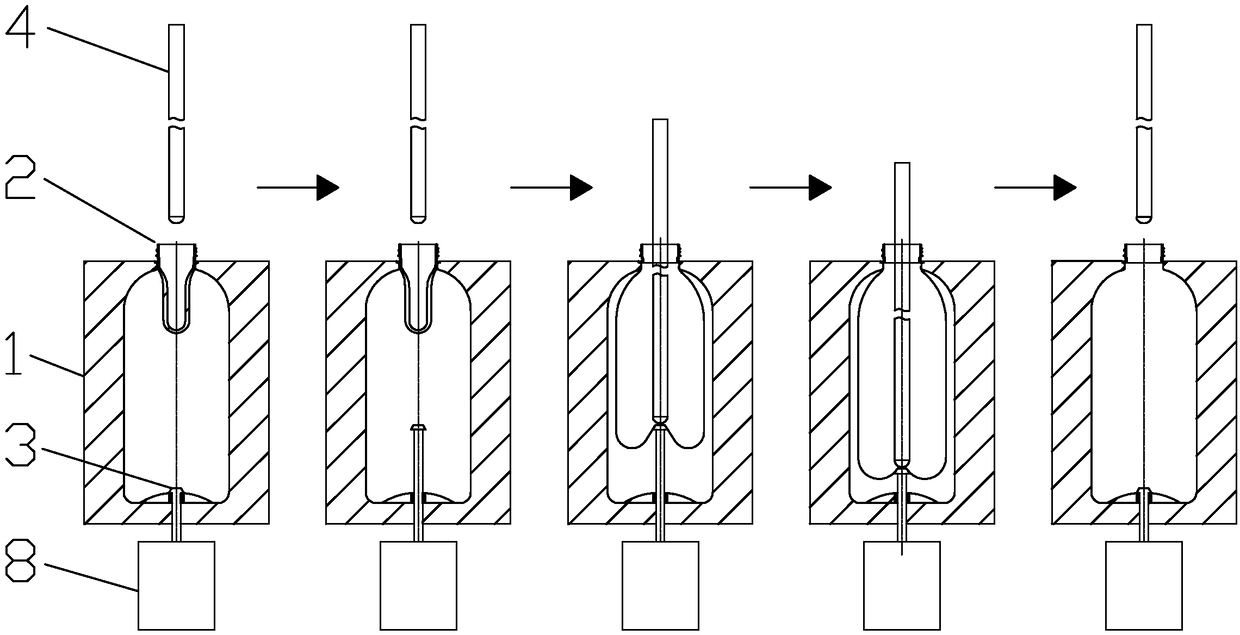
[0025] refer to figure 1 , what this embodiment discloses is a method for positioning stretch hollow blow molding in both axial and bidirectional directions. The supporting device includes a supporting rod 3 arranged at the center of the bottom of the mold cavity 1 and a driving mechanism I8 that drives the supporting rod 3 to perform telescopic movement. The top of the supporting rod 3 is a platform that will not pierce the bottom of the preform , the driving mechanism I8 is a pneumatic cylinder or a hydraulic cylinder.
[0026] Its blow molding container molding includes the following steps:
[0027] Step 1: Heat the preform 2 to the stretching temperature, and then put it into the blow molding cavity 1 for axial stretching with the help of the stretch rod 4, and at the same time inject low air pressure at the mouth of the preform 2, and pre-blow molding while stretching , this step is basically the same as the traditional stretch blow molding method;
[0028] Step 2, whe...
Embodiment 2
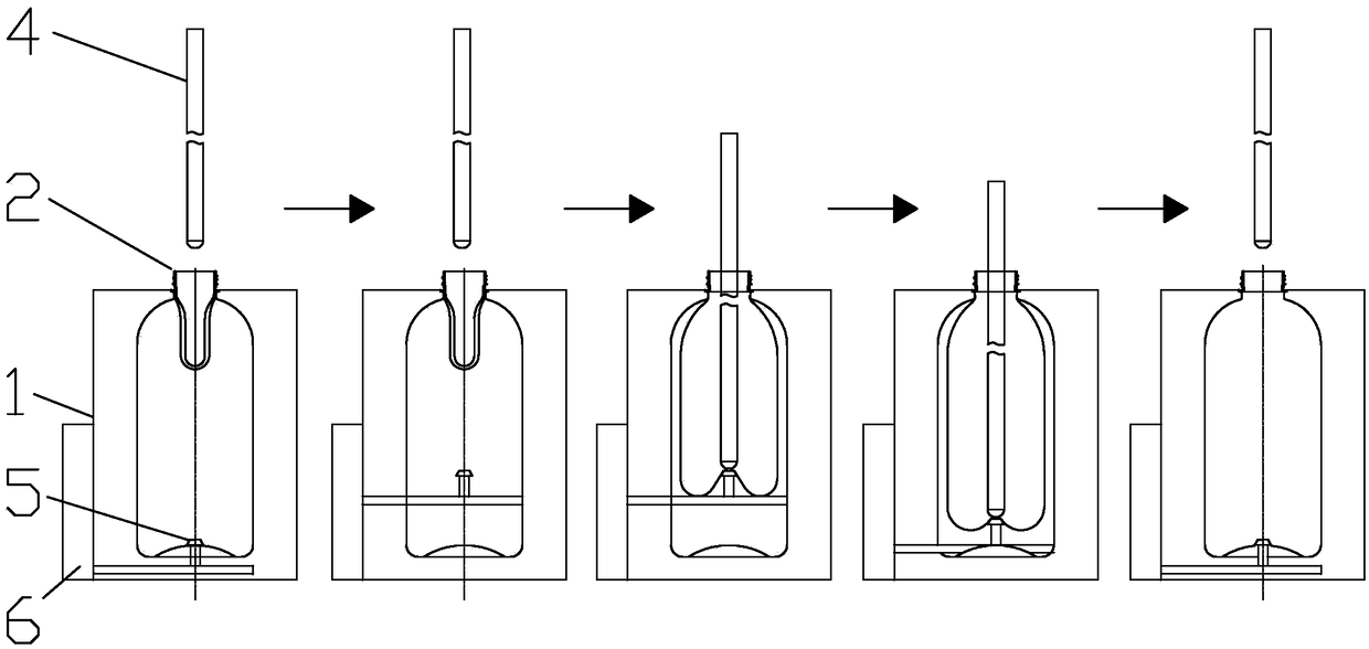
[0032] refer to figure 2 , the method adopted in this embodiment is basically the same as that in Embodiment 1, and the only difference lies in the supporting device. The supporting device includes a push rod 5 arranged in the middle of the mold cavity 1 and a drive mechanism II6 that drives the push rod 5 to move up and down. Both sides of the push rod 5 are installed on the inner side wall of the mold cavity 1, and the drive mechanism II6 is a pneumatic cylinder, a hydraulic cylinder or a motor and drives the ejector rod 5 to move up and down. The molding steps of the blow-molded container in this embodiment are basically the same as those in Embodiment 1.
Embodiment 3
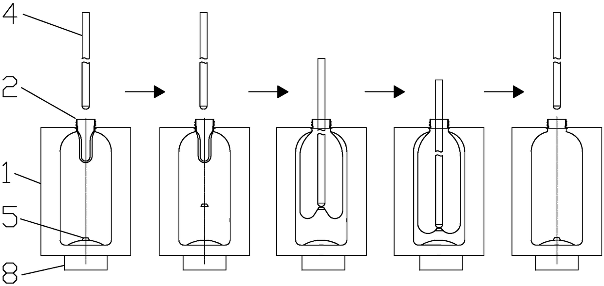
[0034] refer to image 3 , the principle of the method adopted in this embodiment is the same as that of the second embodiment, except that the way of the driving mechanism II6 is different. In this embodiment, the driving mechanism II6 is an electromagnet with variable magnetic poles. N pole, the lower end is the magnetic material of S pole, and this magnetic material is top-light and foot-heavy to avoid turning over when rising, and the purpose of controlling the movement of the push rod 5 up and down can be achieved by changing the magnetic pole of the electromagnet.
[0035] In the second step of forming the blow molding container, when stretching to the position of the supporting device, the ejector rod 5 has been suspended in the middle under the action of the electromagnet, and supports the center of the bottom of the preform that has been gradually stretched and expanded. At this time, the stretching rod 4 slows down the stretching speed or suspends stretching, and the...
PUM
 Abstract
Description
Claims
Application Information
 - R&D
- Intellectual Property
- Life Sciences
- Materials
- Tech Scout
- Unparalleled Data Quality
- Higher Quality Content
- 60% Fewer Hallucinations
Browse by: Latest US Patents, China's latest patents, Technical Efficacy Thesaurus, Application Domain, Technology Topic, Popular Technical Reports.
© 2025 PatSnap. All rights reserved.Legal|Privacy policy|Modern Slavery Act Transparency Statement|Sitemap|About US| Contact US: help@patsnap.com


