Rotor and compressor

A technology of rotor and iron core, which is applied in the field of compressors and can solve problems such as potential safety hazards of compressors

Pending Publication Date: 2019-03-08
ZHUHAI GREE REFRIGERATION TECH CENT OF ENERGY SAVING & ENVIRONMENTAL PROTECTION
View PDF0 Cites 0 Cited by
  • Summary
  • Abstract
  • Description
  • Claims
  • Application Information

AI Technical Summary

Problems solved by technology

[0005] Based on this, it is necessary to provide a rotor and compressor that can reduce safety hazards in view of the problem that traditional compressors have relatively large safety hazards.

Method used


Image

  • Rotor and compressor
  • Rotor and compressor
  • Rotor and compressor

Examples


Embodiment Construction

[0032] In order to facilitate the understanding of the present invention, the present invention will be described more fully below with reference to the relevant drawings. The preferred embodiments of the invention are shown in the drawings. However, the present invention can be implemented in many different forms and is not limited to the embodiments described herein. On the contrary, the purpose of providing these embodiments is to make the understanding of the disclosure of the present invention more thorough and comprehensive.

[0033] It should be noted that when an element is referred to as being "fixed to" another element, it can be directly on the other element or a central element may also exist. When an element is considered to be "connected" to another element, it can be directly connected to the other element or an intermediate element may be present at the same time. The terms "vertical", "horizontal", "left", "right" and similar expressions used herein are for ill...


PUM


Abstract

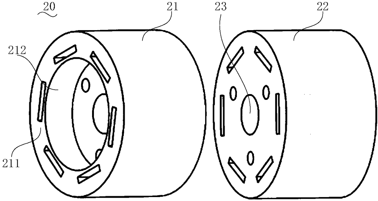
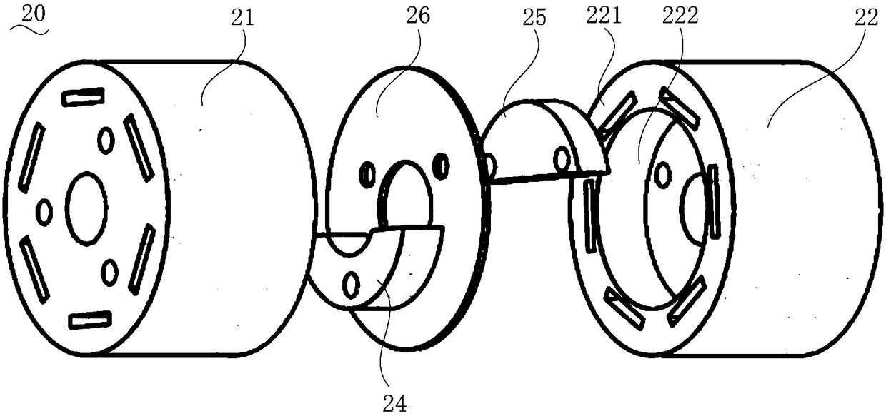
The invention relates to a rotor and a compressor. The rotor comprises a first iron core, a second iron core, a first balance block and a second balance block, wherein the second iron core and the first iron core are concentrically arranged and are same in outer diameter; the second iron core and the first iron core are connected in an axial direction of the rotor and are penetrated to form a crankshaft assembly hole; the first balance block and the second balance block are different in mass; a first containing hole is formed in a first axial end surface of the first iron core; the first containing hole concentrically surrounds the crankshaft assembling hole; the first balance block is at least partially contained in the first containing hole; the second balance block is assembled on a second axial end surface of the second iron core; and the first balance block and the second balance block are located on the two opposite sides of one diameter of the crankshaft assembly hole respectively. The first balance block is at least partially contained in the first containing hole, so that the probability of generating interference between the first balance block and a pump body of the compressor can be reduced, and potential safety hazards are reduced.

Description

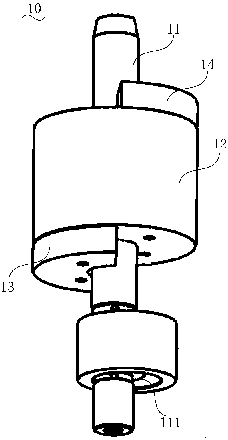
Technical field [0001] The invention relates to the technical field of compressors, in particular to a rotor and a compressor. Background technique [0002] Due to the working principle of the compressor, the rotor 10 of the compressor (refer to figure 1 An eccentric part 111 is designed on the crankshaft 11 of) to realize the function of the compressor. The roller is sleeved outside the eccentric part. When the crankshaft 11 rotates, the eccentric part 111 drives the roller to move. Due to the distance between the centroid of the eccentric part 111 and the roller and the axis of rotation of the crankshaft 11, when the compressor is running, the eccentric part 111 and the roller will generate an unbalanced rotating centrifugal force, thereby generating a torque, prompting the entire The compressor vibrates. [0003] In order to balance the aforementioned rotating centrifugal force and its torque, a main balance weight 13 and an auxiliary balance weight 14 are protrudingly provided...

Claims


Application Information

Patent Timeline
Patent Type & Authority Applications(China)
IPC IPC(8): H02K7/04H02K7/075
CPCH02K7/04H02K7/075
Inventor 韩东岳江胜军张强郑学良
Owner ZHUHAI GREE REFRIGERATION TECH CENT OF ENERGY SAVING & ENVIRONMENTAL PROTECTION
Why Eureka
Try Eureka