
Neutral point grounding device and control method thereof

A neutral point grounding and control method technology, applied in the field of power transmission and distribution, can solve the problems of unfavorable personal safety, large fault current, and large ground fault current, so as to ensure personal safety, increase fault characteristics, and small fault current Effect

Active Publication Date: 2019-03-08
CHINA ELECTRIC POWER RES INST +3
View PDF5 Cites 1 Cited by
  • Summary
  • Abstract
  • Description
  • Claims
  • Application Information

AI Technical Summary

Problems solved by technology

Different grounding methods have their own advantages and disadvantages: the neutral point non-grounding method allows continuous operation for 2 hours when the single-phase is grounded, but when the grounding current exceeds a certain value, the arc cannot be self-extinguished, and it is easy to generate arc grounding overvoltage; neutral grounding The grounding method through the arc-suppression coil can compensate the large capacitive current generated by the power grid, but it may cause resonance overvoltage due to inaccurate measurement of the capacitive current and improper compensation. When the capacity of the arc-suppression coil does not meet the requirements, it needs to be upgraded. ;The grounding current is large when the neutral point is grounded by low resistance, which is beneficial to the fault line selection, but the tripping rate is high, the local resistance value is too small, and the grounding fault current is large, which brings safety hazards to equipment, communication lines and personal safety.
The resistors connected in parallel to the arc suppression coil are all fixed resistors. If the resistance value is large, the sensitivity will be low. If the resistance value is small, the fault current will be large, which is not conducive to personal safety.
In addition, the selection of fault characteristics is mainly based on the magnitude of the zero-sequence current, and when the transition resistance is large, only the magnitude of the zero-sequence current cannot effectively distinguish the fault line

Method used


Image

  • Neutral point grounding device and control method thereof
  • Neutral point grounding device and control method thereof

Examples


Embodiment Construction

[0023] The present invention will be further described below in conjunction with the accompanying drawings and specific embodiments, so that those skilled in the art can better understand the present invention and implement it, but the examples given are not intended to limit the present invention.

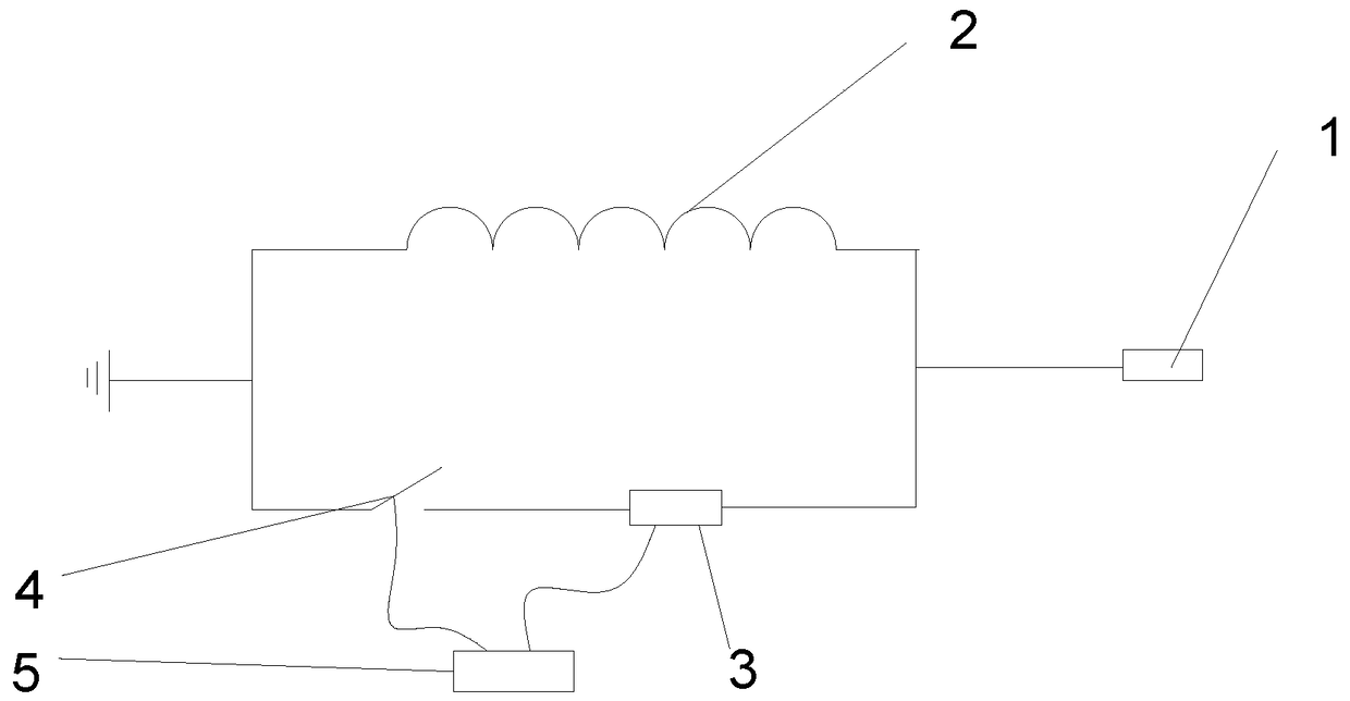
[0024] A neutral point grounding device such as figure 1 shown, including:

[0025] Arc suppression coil 2, one end of which is connected to neutral point 1, and the other end is grounded;

[0026] The resistance unit is connected in parallel with the arc suppressing coil 2, and is used to provide a resistance whose resistance value can be changed;

[0027] The controller 5 is used to control the resistance value of the resistance unit and the on-off of the resistance unit circuit.

[0028] In an optional implementation manner of this embodiment, the resistance unit includes: a switch 4 and an adjustable resistance 3 connected in series, and the controller 5 is respectively conn...


PUM


Abstract

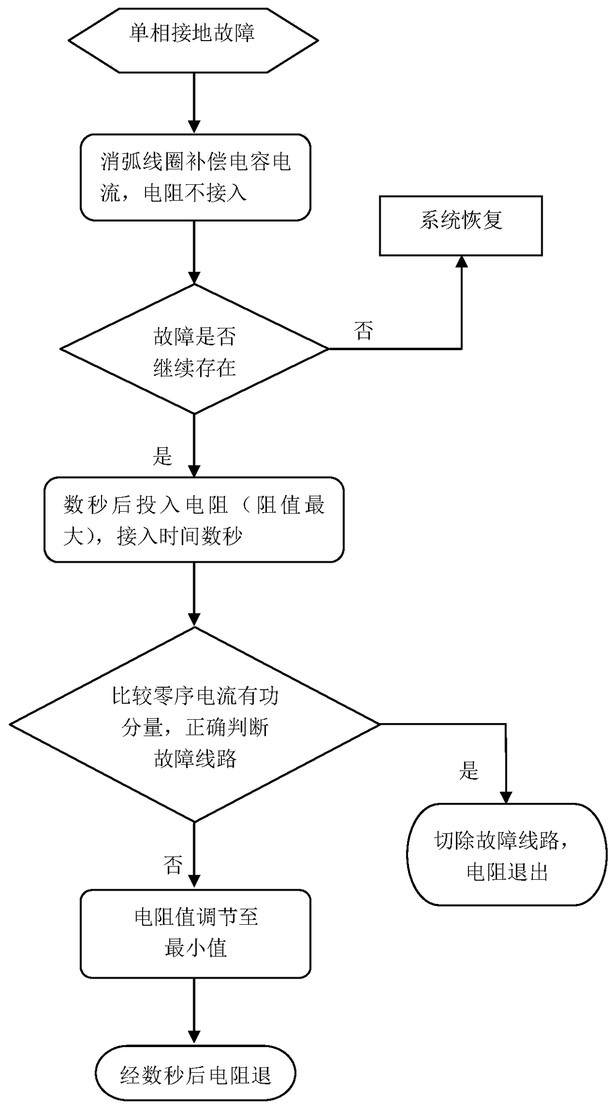
The invention provides a neural point grounding device and a control method thereof. The neural point grounding device comprises an arc suppression coil with one end connected with the neural point and the grounded other end; a resistor unit in parallel connect with the arc suppression coil and used for providing a resistor capable of changing a resistance; a controller for controlling the resistance of the resistor unit and the on-off of the resistor unit circuit. Through the neural point grounding device and the control method thereof provided by the invention, the resistance is maximal wheninputting an adjustable resistor at the primary input, the line metallicity grounding fault and the middle and low resistance grounding fault with large proportion can be judged, the fault current issmall, and the personal safety is guaranteed; for tiny minority of grounding fault with transition resistor as high resistance, the fault line is not distinguished, the adjustable resistor can be automatically adjusted to the minimum, the fault feature is further increased, and an accuracy rate of the fault selection is improved.

Description

technical field [0001] The invention relates to the technical field of power transmission and distribution, in particular to a neutral point grounding device and a control method thereof. Background technique [0002] The neutral point grounding methods of the power grid include: non-grounding method, grounding through arc suppressing coil and low resistance grounding. Different grounding methods have their own advantages and disadvantages: the neutral point non-grounding method allows continuous operation for 2 hours when the single-phase is grounded, but when the grounding current exceeds a certain value, the arc cannot be self-extinguished, and it is easy to generate arc grounding overvoltage; neutral grounding The grounding method through the arc-suppression coil can compensate the large capacitive current generated by the power grid, but it may cause resonance overvoltage due to inaccurate measurement of the capacitive current and improper compensation. When the capacit...

Claims


Application Information

Patent Timeline
IPC IPC(8): H02H9/08
CPCH02H9/08
Inventor 李振强陈维江谭波田野戴敏范冕周姣查志鹏王磊何慧雯李辉彭庆华
Owner CHINA ELECTRIC POWER RES INST
Learn More