
Noncontact current measuring device suitable for intelligent power grid protection system

A current measuring device, non-contact technology, applied in the direction of measuring devices, only measuring current, measuring electrical variables, etc., can solve problems such as unsuitable for large current measurement of fixed devices, unable to detect current information of AC system, etc.

Active Publication Date: 2019-03-08
UNIV OF ELECTRONICS SCI & TECH OF CHINA
View PDF6 Cites 13 Cited by
  • Summary
  • Abstract
  • Description
  • Claims
  • Application Information

AI Technical Summary

Problems solved by technology

But it cannot detect the current information of the AC system
On the other hand, the error caused by using the sensor array to eliminate interference will be affected by the relative position error of the conductor to be measured and the array
[0007] In the Chinese invention patent application published on May 25, 2018, the publication number is CN108072780A, a handheld type non-contact current measurement system is disclosed, which is also only suitable for measuring alternating current, and is not suitable for fixed in the power system. Device for high current measurement

Method used


Image

  • Noncontact current measuring device suitable for intelligent power grid protection system
  • Noncontact current measuring device suitable for intelligent power grid protection system
  • Noncontact current measuring device suitable for intelligent power grid protection system

Examples


specific example

[0040] 1. Numerical and finite element simulation

[0041] Firstly, the feasibility of eliminating the error caused by the interference of the present invention is verified by numerical analysis.

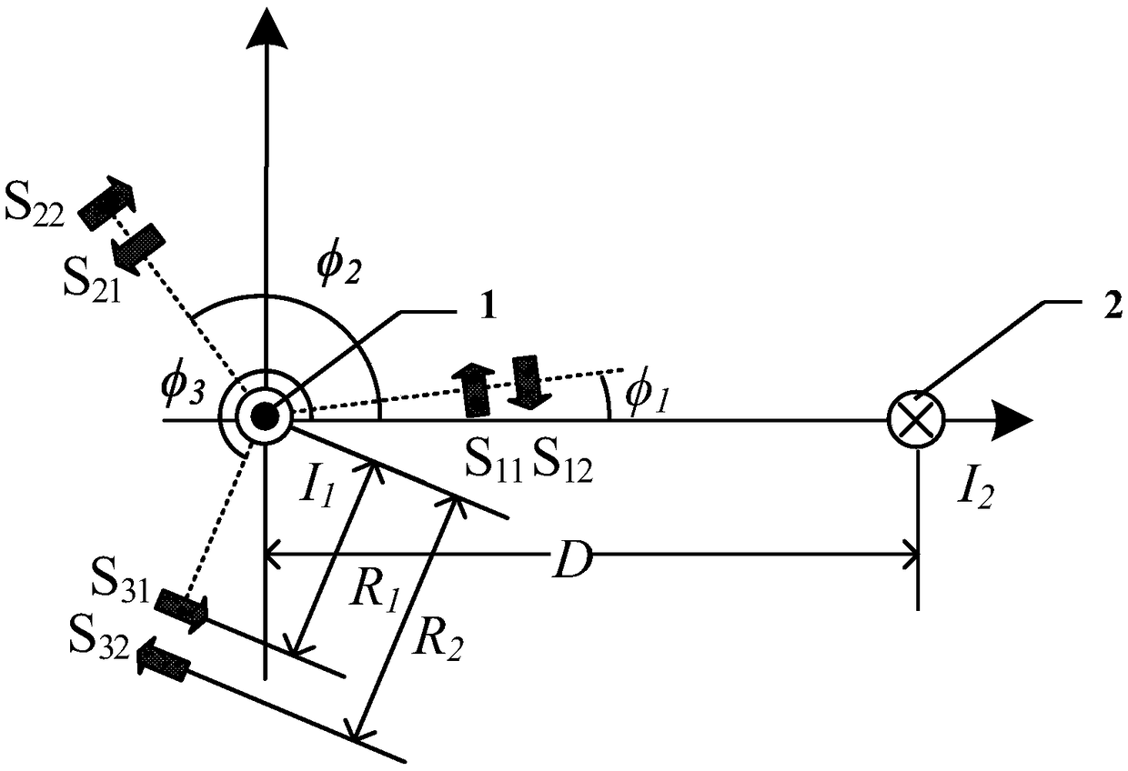
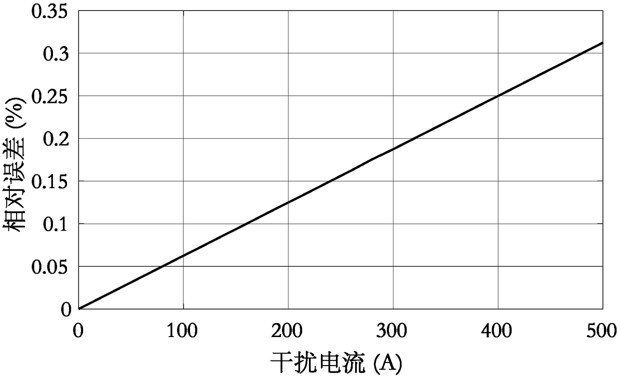
[0042] Suppose the current to be measured I 1 and interference current I 2 For direct current, the current direction is opposite, I 1 for 500A. R 1 0.03m, R 2 It is 0.04m. Interference current I 2 to the measured current I 1 The distance is 0.3m. When the interference current I 2 When changing from 100A to 500A, the result is as follows figure 2 shown. It can be seen that when the disturbance current I 2 When increasing, the measured current I 1 The relative error between the measured value and the true value also increases. But the maximum relative error is still less than 0.35%.

[0043] Suppose the current to be measured I 1 and interference current I 2 For AC and equal in size, when the current changes from 100sin (100πt) to 500sin (100πt), the root mean square...


PUM


Abstract

The invention discloses a noncontact current measuring device suitable for an intelligent power grid protection system. The noncontact current measuring device is constructed by three sets of tunneling magnetic resistance effect sensor (TMR sensor) arrays which are distributed in one circle. Each set of TMR sensor array is composed of two TMR sensors which have parallel magnetic sensitivity and opposite directions. The phase angle between the TMR sensor arrays is 120 DEG. The TMR sensor is parallel with the tangential line of the circle. The distances between the TMR sensors to the circle center are same. The measuring point positions which are separated from the circle centers for R1 and R2 in two TMR sensors of each set of TMR sensor array are used for measuring magnetic flux density ofa magnetic field that is generated by a current carrying conductor at the measuring point points. The current of the current carrying conductor can be obtained according to six magnetic flux densitiesthrough an equation set solving mode. Furthermore, the magnetic field which is generated by interference current of surrounding electrical equipment and the interference from a geomagnetic field areneutralized. The noncontact current measuring device is particularly suitable for current monitoring of a certain phase in a ground fault line selection in a DC or AC condition.

Description

technical field [0001] The invention belongs to the technical field of power grid current measurement, and more specifically relates to a non-contact current measurement device suitable for a smart grid protection system, in particular to current monitoring for ground fault line selection in the smart grid protection system. Background technique [0002] The development of traditional power grids to modern smart grids has put forward higher requirements for the stability of power grids, which has led to a lot of research on new voltage and current measurement devices for monitoring, protection and control purposes. Fault current is one of the important factors that threaten the stable operation of the power grid. Real-time and accurate monitoring of fault current is of great significance to ensure the stable operation of the power grid. [0003] In the distribution network, when a ground fault occurs in the non-effectively grounded system, it will affect the safety and stabi...

Claims


Application Information

Patent Timeline
Patent Type & Authority Applications(China)
IPC IPC(8): G01R19/00
CPCG01R19/0092
Inventor 黄琦陈亚锋赫瓦贾.阿尔萨兰.哈比卜井实李坚张真源胡维昊蔡东升易建波
Owner UNIV OF ELECTRONICS SCI & TECH OF CHINA
Learn More