Water-cooling premixed combustion method and device

A premixed combustion and water cooling technology, applied in the direction of combustion method, burner, combustion type, etc., can solve the problems of large furnace size and large NOx emissions, and achieve the effects of small furnace, reduced NOx emissions, and high safety

Pending Publication Date: 2019-03-08
浙江力巨热能设备有限公司
View PDF0 Cites 1 Cited by
  • Summary
  • Abstract
  • Description
  • Claims
  • Application Information

AI Technical Summary

Problems solved by technology

[0006] The purpose of the present invention is to provide a water-cooled premixed combustion method and device in order to solve the problems of large NOx emissions and large furnace size of traditional burners

Method used


Image

  • Water-cooling premixed combustion method and device
  • Water-cooling premixed combustion method and device
  • Water-cooling premixed combustion method and device

Examples


Embodiment 1

[0032] This embodiment provides a water-cooled premixed combustion method, comprising the following steps:

[0033] S1, the burner 13 extends into the interior of the furnace 14 to form an annular combustion tube 15, and the gas and air are premixed in the annular combustion tube 15 to form a mixed gas;

[0034] S2, the mixed gas is ejected through the end outer wall of the annular combustion tube 15, and the air velocity is greater than the combustion velocity;

[0035] S3, the mixed gas burns close to the water wall 9 to form a main flame.

[0036] Different from the traditional water-cooled premixed combustion method, in this embodiment, the mixed gas in the burner 13 is sprayed from the end outer wall of the annular combustion cylinder 15, and the speed of the jetted air flow is greater than the combustion speed, and the mixed gas is close to the water-cooled wall 9 burn to form the main flame. Not only can the combustion flame be stabilized through the water wall 9, so ...

Embodiment 2

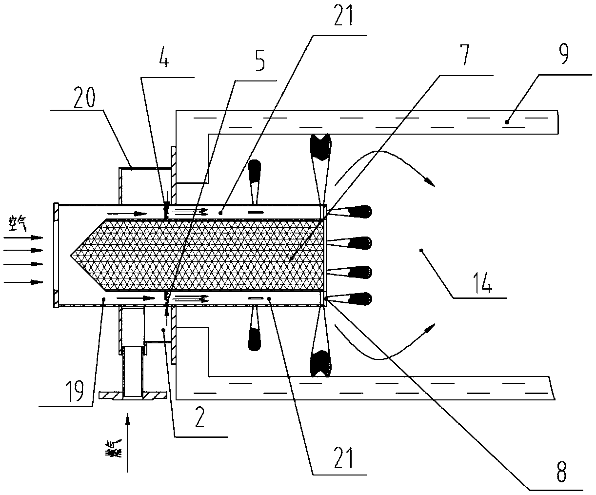
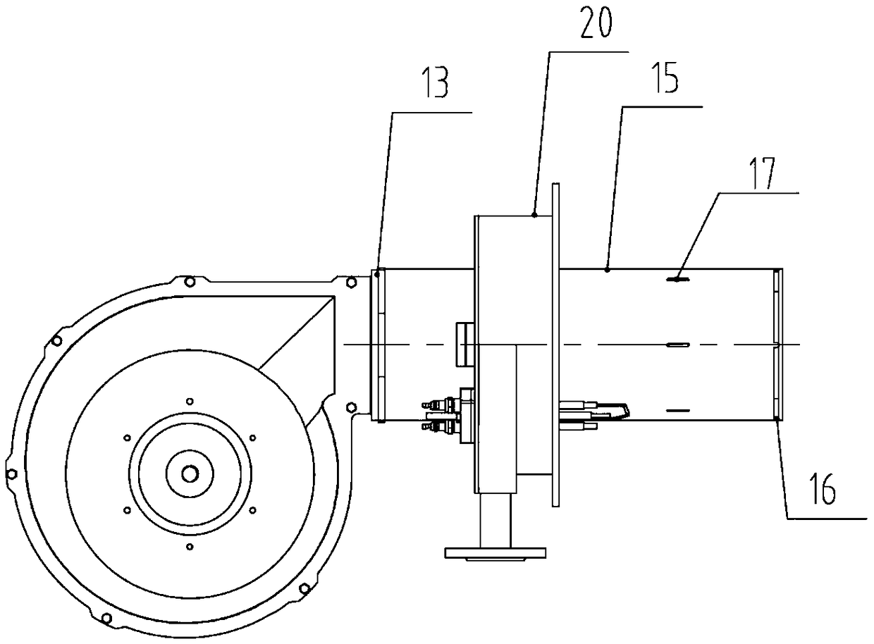
[0040] Such as Figure 1-3 As shown, this embodiment provides a water-cooled premixed combustion device, including a burner 13 and a furnace 14 , and the burner 13 extends into the furnace 14 to form an annular combustion tube 15 . The front end of annular combustion tube 15 is provided with air inlet and gas inlet, and air and combustion gas form mixed gas in annular combustion tube 15, and the end outer wall of annular combustion tube 15 is provided with the outlet hole 16 of mixed gas. The mixed gas is sprayed out from the outlet hole one 16 to form a main flame, and the main flame is perpendicular to the annular combustion tube 15 . The inner wall of the furnace 14 is a water-cooled wall 9, and the mixed gas burns close to the water-cooled wall 9 to form a main flame. The opening shape of air outlet one 16 can be annular seam, circular hole, square hole etc.

[0041] When the mixed gas is ejected from the outlet hole one 16, the air velocity of the mixed gas is controlle...


PUM


Abstract

The invention provides a water-cooling premixed combustion method and a device. The method comprises the following steps that the combustor extends into the hearth to form an annular combustion cylinder, and the fuel gas and the air are premixed in the annular combustion cylinder to form mixed gas; the mixed gas is sprayed out through the outer wall of the tail end of the annular combustion cylinder, and the air flow speed is larger than the combustion speed; the mixed gas is combusted at the water cooling wall of the hearth to form a main flame; and the distance between the water cooling wallof the hearth and the outer wall of the annular combustion cylinder is 200-600 mm. According to the water-cooling premixed combustion method and the device, an air outlet hole I is arranged in the outer wall of the tail end of the annular combustion cylinder, and the water cooling wall is located at a portion, a certain distance from the outer wall, of the annular combustion cylinder, so that theflame can be stably combusted through the water cooling wall, the premixed gas is converted into stable combustion from unstable combustion in a flamelifting state at one position of the air outlet hole I, the mixed gas can be close to the water cooling wall for combusting, the combustion temperature of the flame is reduced through the water cooling wall, and then NOx emission is reduced.

Description

technical field [0001] The invention relates to the technical field of combustion devices, in particular to a water-cooled premixed combustion method and device. Background technique [0002] Nitrogen oxides form acid rain, which is one of the components of air pollutants and one of the main components of smog. Beijing has promulgated a new "Emission Standard of Air Pollutants for Boilers", which stipulates that starting from April 1, 2017 , the NOx emission limit of all gas-fired boilers in use is 80mg / m 3 , The emission limit of nitrogen oxides from new gas-fired boilers is 30mg / m3, which puts forward low-nitrogen requirements for current combustion devices. [0003] The current low-nitrogen combustion control technology mainly reduces the formation of nitrogen oxides by reducing the flame temperature. According to the formation mechanism of NOx, it can be divided into thermal nitrogen oxides, fuel nitrogen oxides and rapid nitrogen oxides. Among them, fuel-type nitroge...

Claims


Application Information

Patent Timeline
Patent Type & Authority Applications(China)
IPC IPC(8): F23D14/02F23D14/78
CPCF23D14/02F23D14/78
Inventor 何剑沈炳元李惠臻邱周春
Owner 浙江力巨热能设备有限公司
Why Eureka
Try Eureka