
Anti-blocking fire emergency lighting indicating device

An indicator device and fire emergency technology, applied in lighting devices, lighting devices, lighting auxiliary devices, etc., can solve the problems of simple structure of fire emergency lights, equipment light blocking, and affecting light transmission, so as to ensure smooth air circulation and improve practicality. sexual effect

Active Publication Date: 2019-03-08
江门市蓬江区虹源电子有限公司
View PDF9 Cites 8 Cited by
  • Summary
  • Abstract
  • Description
  • Claims
  • Application Information

AI Technical Summary

Problems solved by technology

[0003] Existing fire emergency lights are simple in structure and single in function. Emergency lights are usually directly exposed outside the equipment. Therefore, when they are not used for a long time, the surface of the lamps is easy to be stained with dust, which affects the transmission of light, resulting in a decrease in lighting brightness. In addition, in the event of a fire, due to The smoke at the fire scene is thick, and the soot is easily adsorbed on the surface of the lighting lamp, and it is prone to collapse during a fire. Some obstacles (such as wood boards and stones) are easy to block the front of the lighting lamp, causing the light emitted by the equipment to be blocked and cannot work normally. Instruct people to exit safely, thereby reducing the practicality of existing fire emergency lights

Method used


Image

  • Anti-blocking fire emergency lighting indicating device
  • Anti-blocking fire emergency lighting indicating device
  • Anti-blocking fire emergency lighting indicating device

Examples


Embodiment Construction

[0025] The present invention is described in further detail now in conjunction with accompanying drawing. These drawings are all simplified schematic diagrams, which only illustrate the basic structure of the present invention in a schematic manner, so they only show the configurations related to the present invention.

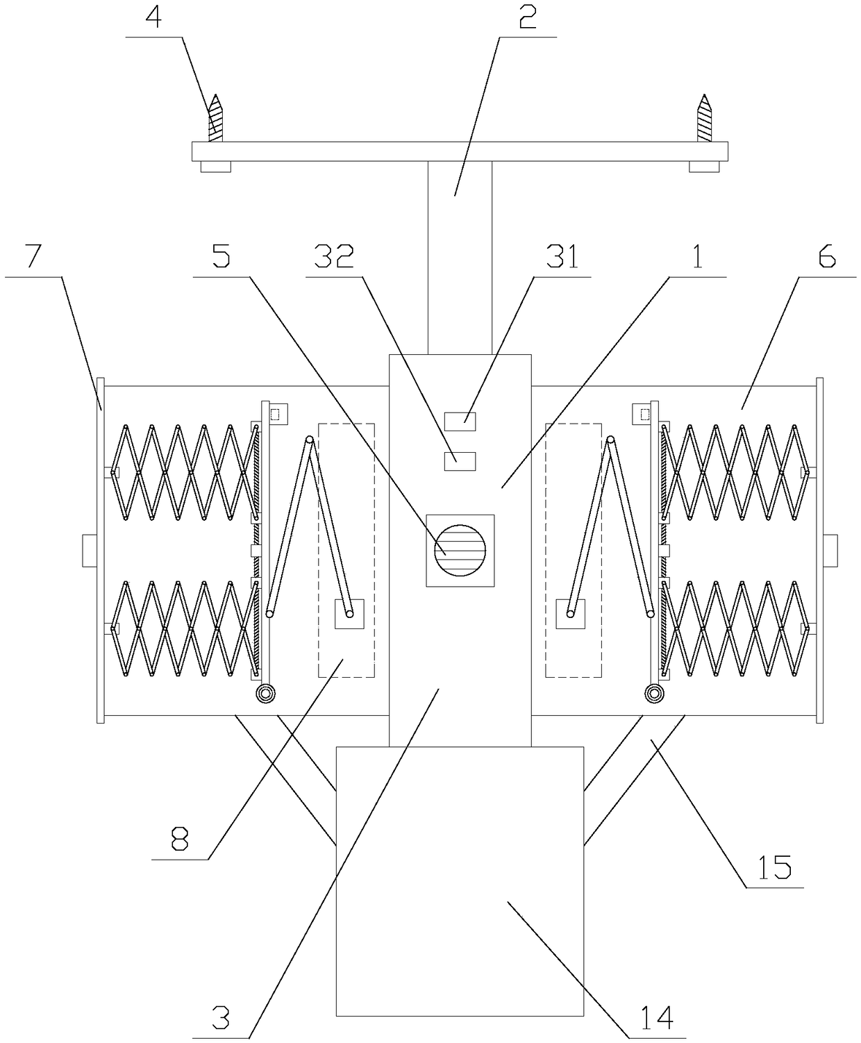
[0026] Such as figure 1 As shown, an anti-blocking fire emergency lighting indicator device includes a top plate 1, a boom 2, a main body 3, a ventilation mechanism, two indicating mechanisms and four screws 4, and the screws 4 are arranged at the four corners of the top plate 1, The main body 3 is fixed below the top plate 1 through the suspender 2, the ventilation mechanism is arranged under the main body 3, and the two indicating mechanisms are respectively located on both sides of the main body 3, the main body 3 is provided with a PLC, and the main body 3 3 is provided with a speaker 5, and the speaker 5 is electrically connected to the PLC;

[0027] In...


PUM


Abstract

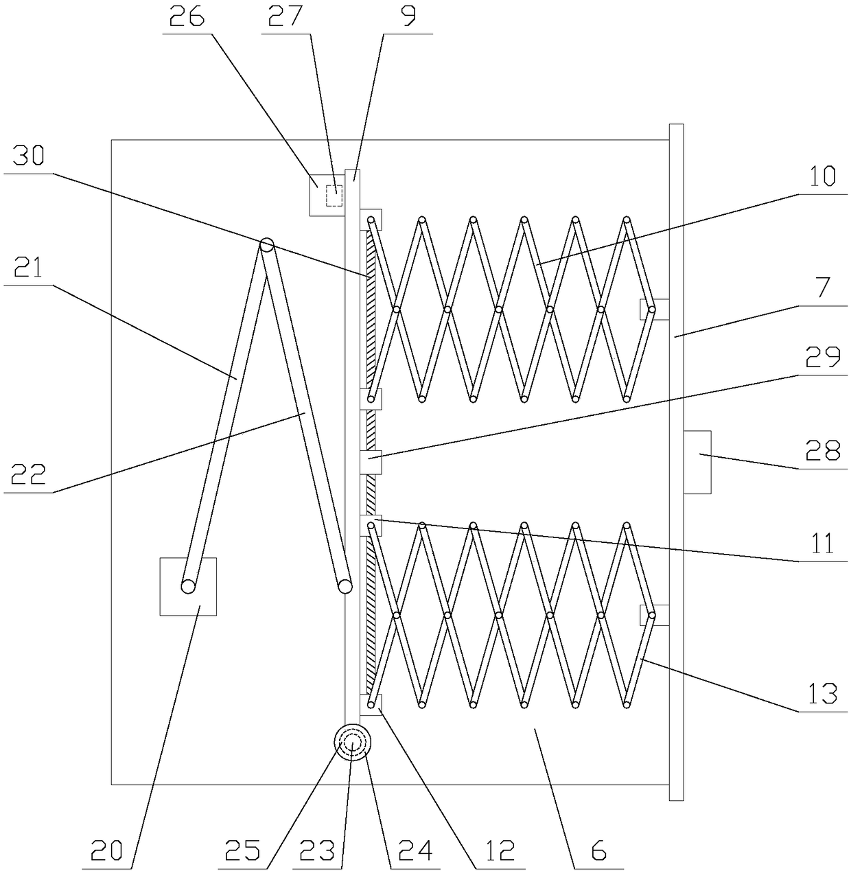
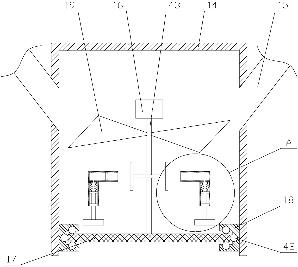
The invention relates to an anti-blocking fire emergency lighting indicating device which comprises a top plate, a hanging rod, a main body, a ventilating mechanism, two indicating mechanisms and fourscrews. Each indicating mechanism comprises an indicating box, a sealing plate, an indicating light and two adjusting assemblies; each adjusting assembly comprises a rotating unit, a flat plate, a hinge unit, a drive unit and two telescopic units; the ventilating mechanism comprises a ventilating pipe and two branch pipes; and a first motor, a rotary shaft, a filter screen, a vibrating assembly,a support frame and two fan blades are arranged in the ventilating pipe. According to the anti-blocking fire emergency lighting indicating device, a dustproof effect can be achieved through the sealing plates in the indicating mechanisms, and the sealing plates can move to push front obstacles away when the fire happened, so that light rays emitted by the indicating lights are prevented from beingblocked, and people is guided to escape safely; and in addition, the indicating boxes can spray air flows through the ventilating mechanisms so as to blow away soot nearby, so that the occurrence ofthe phenomenon that the soot is adsorbed on the surfaces of the indicating lights so as to influence lighting is prevented, and the practicability of the equipment is improved.

Description

technical field [0001] The invention relates to the field of fire emergency equipment, in particular to an anti-blocking fire emergency lighting indicator device. Background technique [0002] The fire emergency light is suitable for fire emergency lighting and is the most common lighting tool for fire protection. It has a long emergency time, high brightness, and automatic power-off function. Fire emergency lights have the characteristics of low power consumption, high brightness, and long service life. There are power switches and indicator lights on the side, which are suitable for public production in factories, hotels, schools, and units for emergency lighting. [0003] Existing fire emergency lights are simple in structure and single in function. Emergency lights are usually directly exposed outside the equipment. Therefore, when they are not used for a long time, the surface of the lamps is easy to be stained with dust, which affects the transmission of light, resulti...

Claims


Application Information

Patent Timeline
Patent Type & Authority Applications(China)
IPC IPC(8): F21S9/02F21V17/12F21V17/16F21V21/02F21V21/22F21V31/00F21V33/00
CPCF21S9/022F21V17/12F21V17/162F21V21/02F21V21/22F21V31/00F21V33/0096
Inventor 张宇
Owner 江门市蓬江区虹源电子有限公司
Learn More