Horizontal reaction kettle and shaft sealing device for horizontal reaction kettle

A horizontal reaction kettle and shaft sealing technology, applied in the direction of engine sealing, engine components, mechanical equipment, etc., can solve problems such as affecting normal production, weakening sealing effect, shaft sealing wear, etc., achieving remarkable sealing effect, convenient loading and unloading, simple structure

Active Publication Date: 2019-03-08
WEIHAI CHEM MACHINERY
View PDF9 Cites 0 Cited by
  • Summary
  • Abstract
  • Description
  • Claims
  • Application Information

AI Technical Summary

Problems solved by technology

In the production process, the stirring shaft of the horizontal reactor generally has a large shaft diameter and is buried in the reaction material, so there is a problem of difficult sealing. At present, after the shaft sealing device of the horizontal reactor is installed and operated for a period of time, due to the infiltration of the reaction material , high-heat gas penetration and high-temperature heat conduction and other adverse factors, the shaft seal wears, ages, and deforms prematurely, making it difficult to maintain the seal, and the sealing effect is accelerated and weakened to failure, affecting normal production

Method used


Image

  • Horizontal reaction kettle and shaft sealing device for horizontal reaction kettle
  • Horizontal reaction kettle and shaft sealing device for horizontal reaction kettle
  • Horizontal reaction kettle and shaft sealing device for horizontal reaction kettle

Examples


Embodiment 1

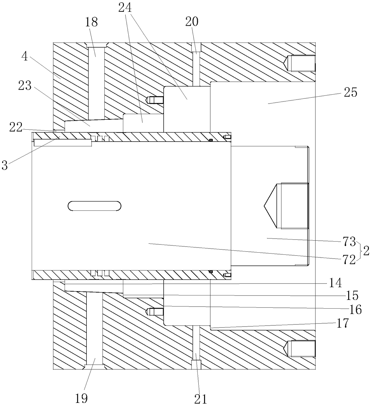
[0050] Depend on figure 1 As shown, the present invention provides a shaft sealing device for a horizontal reaction kettle, which is provided with a shaft head 2, and a shaft sleeve 3 is fixedly sleeved on the shaft head 2, and a support seat 4 is provided outside the shaft sleeve 3, and the support seat 4 It may be a cylindrical structure, and a sealing structure assembly is provided between the outer peripheral surface of the shaft sleeve 3 and the inner peripheral surface of the support seat 4 . A bearing assembly is provided at the end of the shaft head 2. The bearing assembly is provided with a bearing 5, a bearing chamber 6 and a bearing gland 7. The bearing 5 is fixedly sleeved at the end of the shaft head 2, and the bearing 5 is arranged between the bearing chamber 6 and the bearing gland 7. In the enclosed space 53 surrounded by the bearing gland 7 . The bearing chamber 6 is fixedly connected with the support seat 4, the first shaft oil seal 8 is connected between th...

Embodiment 2

[0067] Depend on Figure 31 As shown, the present invention provides a shaft sealing device for a horizontal reactor. On the basis of Embodiment 1, the end of the shaft head 2 is passed through the bearing gland 7 and protruded out. The shaft head 2 and the bearing gland 7 By using the second shaft oil seal 101 for sealing connection, the second shaft oil seal 101 can be a special-shaped oil seal, and the second shaft oil seal 101 is connected with the shaft head 2 in a circumferential sliding manner; the structure, connection relationship, main principle of sealing of other parts of the present invention and The installation method of the shaft sealing device is the same as that of Embodiment 1, and will not be described again, as the shaft sealing device at the other end of the stirring shaft 1 in the horizontal reactor. The end of the shaft head 2 that passes through the bearing gland 7 and protrudes is connected to the power output shaft of the external power drive device....

Embodiment 3

[0069] The horizontal reaction kettle is usually mainly composed of four parts: the kettle body, the stirring shaft with stirring blades, the power drive device and the shaft sealing device. The shaft sealing device is installed on the left and right ends of the kettle body, and the top of the kettle body is opened , The bottom of the kettle body is provided with a discharge port. The shaft sealing device described in Embodiment 1 is installed on the left end face of the still body of this embodiment, and the shaft sealing device described in Embodiment 2 is installed on the right end face of the kettle body; between the shaft sealing devices described in Embodiment 1 and Embodiment 2 The synergistic effect, its structure is simple, easy to disassemble and assemble, can effectively solve the shortcomings of poor sealing effect caused by the infiltration of reaction materials, high-heat gas infiltration and high-temperature heat conduction to the sealing structural components of...


PUM


Abstract

The invention provides a horizontal reaction kettle and a shaft sealing device for the horizontal reaction kettle. The shaft sealing device for the horizontal reaction kettle solves the technical problem that the shaft sealing device of the existing horizontal reaction kettle has a relatively poor sealing effect. The shaft sealing device is provided with a shaft head, wherein a shaft sleeve is fixedly arranged on the shaft head in a sleeving manner; a supporting seat is arranged outside the shaft sleeve in a sleeving manner; a sealing structure component is arranged between the shaft sleeve and the supporting seat; a bearing component is arranged at the tail end part of the shaft head and is provided with a bearing, a bearing housing and a bearing gland; the bearing is fixedly arranged atthe tail end part of the shaft head in a sleeving manner; the bearing is arranged in an airtight space formed by the bearing housing and the bearing gland in an enclosing manner; a first oil seal fora shaft is arranged between the bearing housing and the shaft sleeve in a connecting manner; a cavity is formed by the shaft sleeve, the supporting seat and the bearing housing and is sequentially provided with an annular balance cavity and an annular filler cavity from left to right; a sealing structure component of the annular balance cavity comprises a first sealing ring, a second sealing ring,a first R-shaped oil seal and a second R-shaped oil seal; and a sealing structure component of the annular filler cavity comprises a filler chamber, a filler gland and filler. The shaft sealing device can be widely applied to the technical field of reaction kettles.

Description

technical field [0001] The invention relates to the technical field of reactors, in particular to a shaft sealing device for a horizontal reactor and the horizontal reactor. Background technique [0002] Petrochemical equipment is increasingly becoming large-scale. Large-scale is conducive to the production and manufacturing units to increase output value, reduce costs, and increase economic benefits; stirred reactors are widely used in petroleum, chemical, rubber, pesticides, dyes, medicine, and food to complete vulcanization, Pressure vessels for nitrification, hydrogenation, alkylation, polymerization, condensation and other processes. The main factors affecting the stirring effect of the large-scale stirring reactor include the enlargement of the reactor body, the enlargement of the agitator, the enlargement of the stirring power, the enlargement of the sealing device, the enlargement of each nozzle, etc.; these main factors The influencing factors need to be enlarged a...

Claims


Application Information

Patent Timeline
Patent Type & Authority Applications(China)
IPC IPC(8): F16J15/16F16J15/447
CPCF16J15/162F16J15/447
Inventor 孙健谢孔华韩磊刘忠凯李岩
Owner WEIHAI CHEM MACHINERY
Why Eureka
Try Eureka