Stirring device and stirring system

A stirring device and stirring component technology, applied in biochemical cleaning devices, enzymology/microbiology devices, biochemical instruments, etc., can solve problems such as difficult removal of the tank, difficult maintenance, explosion, etc., to improve the stirring effect and improve the stirring efficiency. Efficiency and easy maintenance

Pending Publication Date: 2021-04-30
通化县东明农牧业发展(集团)有限公司
View PDF5 Cites 0 Cited by
  • Summary
  • Abstract
  • Description
  • Claims
  • Application Information

AI Technical Summary

Problems solved by technology

Among them, straw, vegetable waste and other raw materials are easy to float, which often cause crusting and uneven mixing in biogas projects, which causes great inconvenience to the utilization of such waste
[0003] In addition, because the biogas engineering tank contains flammable gas, it is easy to cause unsafe accidents such as explosion when using an electric stirring device to enter the tank, and because the stirring device is installed in the tank, it is not easy to remove the tank when it is damaged, resulting in difficult maintenance , so it also puts forward new requirements for the use of stirring devices

Method used


Image

  • Stirring device and stirring system
  • Stirring device and stirring system
  • Stirring device and stirring system

Examples


Embodiment 1

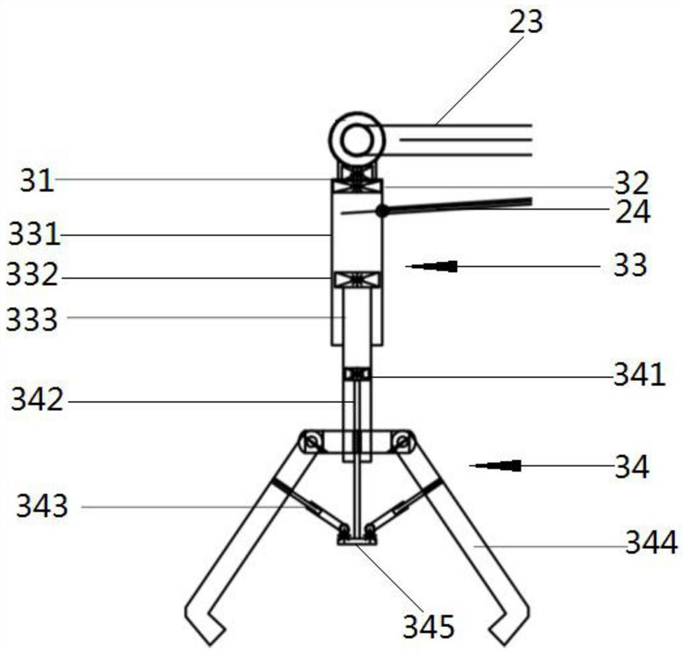
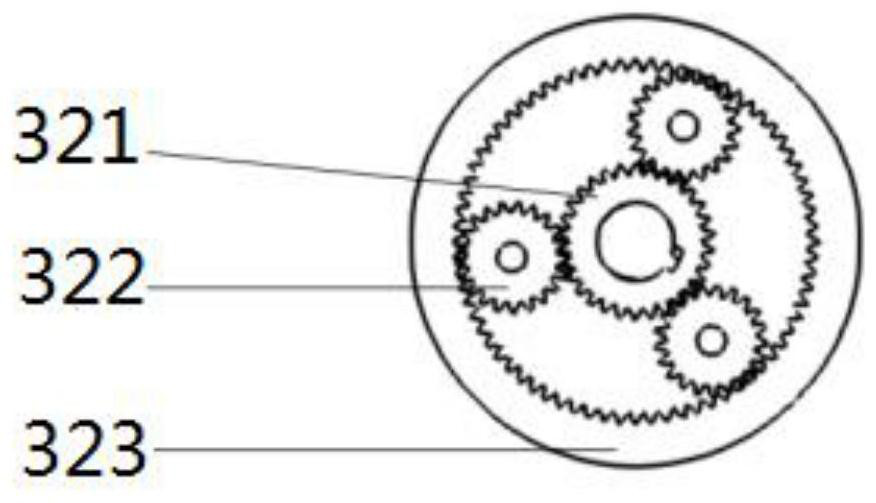
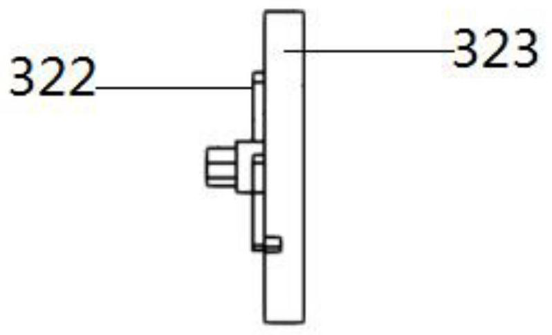
[0029] Such as Figure 1-Figure 4 As shown, this embodiment provides a stirring device, which is mainly used for biogas engineering stirring, including a control element 1, a traction assembly 2 and a stirring assembly 3, the traction assembly 2 is electrically connected to the control element 1, and the stirring assembly 3 is installed on the traction assembly 2 above, and the control element 1 can control the traction assembly 2 to drive the agitation assembly 3 to extend into or out of the biogas engineering tank 4, so as to ensure that when agitation is required, the agitation assembly 3 is controlled to agitate the tank body 4, and when the agitation assembly 3 appears When there is a breakdown or maintenance is required, the stirring assembly 3 is removed for external inspection, which is convenient for maintenance, so as to ensure the smooth progress of the subsequent stirring work, and the stirring assembly 3 can be used at different positions of the same level in the t...

Embodiment 2

[0040] Such as Figure 4 As shown, this embodiment provides a stirring system, including a tank body 4 and the stirring device described in any one of the first embodiment, the tank body 4 is used to place materials, and the side wall of the tank body 4 is provided with a maintenance and the inspection port is opened close to the upper end of the tank body 4 to prevent materials from being discharged through the inspection port. The inspection port is placed, and the traction device can drive the stirring device to extend into or out of the tank body 4 through the inspection port, which is convenient for the inspection of the stirring device, and there is no need to disassemble the tank body 4, so the maintenance is convenient.


PUM


Abstract

The invention discloses a stirring device, which comprises a control element, a traction assembly and a stirring assembly, the traction assembly is electrically connected with the control element, the stirring assembly is installed on the traction assembly, and the control element can control the traction assembly to drive the stirring assembly to extend into or out of a biogas engineering tank body. Wherein the stirring assembly comprises a lifting assembly and a crushing and stirring assembly which are electrically connected with the control element, the lifting assembly is connected with the crushing and stirring assembly and drives the crushing and stirring assembly to ascend and descend, and the crushing and stirring assembly is used for grabbing and stirring crusting materials in the biogas engineering tank body. A stirring system is also disclosed, including a tank body and a stirring device, wherein materials are placed in the tank body, an access hole is formed in the side wall of the tank body and is close to the upper end of the tank body, the access hole can communicate an inner cavity of the tank body with the outside, the stirring device is placed close to the access hole, and the traction device can drive the stirring device to extend into the tank body through the access hole. The stirring device and the stirring system can improve the stirring effect and are convenient to maintain.

Description

technical field [0001] The invention relates to the technical field of biogas fermentation, in particular to a stirring device and a stirring system. Background technique [0002] Under the environment of increasingly mature biogas fermentation technology and environmental protection research, many types of fermented products can be used as raw materials for biogas fermentation and reuse, such as waste from the breeding process, straw and vegetable waste from the planting process, etc. Among them, straw, vegetable waste and other raw materials are easy to float, which often cause incrustation and uneven stirring in the biogas project, which causes great inconvenience to the utilization of such waste. [0003] In addition, because the biogas engineering tank contains flammable gas, it is easy to cause unsafe accidents such as explosion when using an electric stirring device to enter the tank, and because the stirring device is installed in the tank, it is not easy to remove t...

Claims


Application Information

Patent Timeline
Patent Type & Authority Applications(China)
IPC IPC(8): C12M1/02C12M1/33C12M1/107C12M1/00
CPCC12M21/04C12M23/52C12M27/02
Inventor 刘健峰张无敌朴明国张志文杨乐
Owner 通化县东明农牧业发展(集团)有限公司
Why Eureka
Try Eureka