Single-suction single-stage centrifugal fan with high pressure and low flow

A centrifugal fan and small flow technology, which is applied to the components of pumping devices for elastic fluids, mechanical equipment, radial flow pumps, etc., and can solve problems such as unable to regulate gas and invisible object entities

Pending Publication Date: 2019-03-08
ZHENJIANG DANTU DISTRICT FOOD FACTORY
View PDF0 Cites 2 Cited by
  • Summary
  • Abstract
  • Description
  • Claims
  • Application Information

AI Technical Summary

Problems solved by technology

[0003] As we all know, although the structure of the fan is simple, it only consists of the casing, the impeller, the air inlet ring, the air inlet box, and the transmission group. Innovation and creation need to go through many experiments, and simulate working conditions for testing and design modification. It is not difficult for an innovative fan to meet the requirements of performance parameters, but it is very difficult to use the minimum power to meet the performance. Difficult thing

Method used


Image

  • Single-suction single-stage centrifugal fan with high pressure and low flow
  • Single-suction single-stage centrifugal fan with high pressure and low flow
  • Single-suction single-stage centrifugal fan with high pressure and low flow

Examples


Embodiment Construction

[0015] The high-pressure, low-flow single-suction single-stage centrifugal fan of the present invention will be further described in detail below in conjunction with the accompanying drawings and specific embodiments.

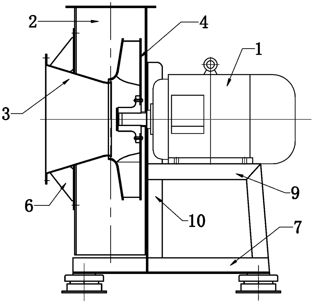
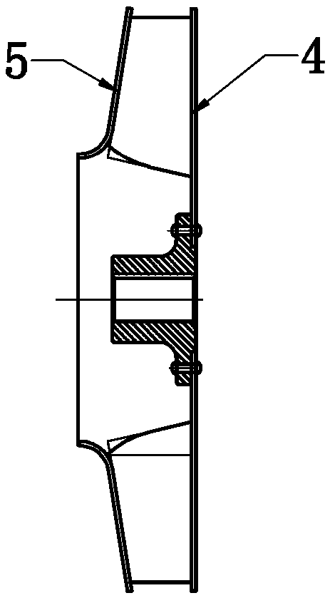
[0016] As shown in the figure, the high-pressure, low-flow single-suction single-stage centrifugal fan of the present invention includes a drive motor 1, a casing 2 and an air inlet ring 3, the main shaft of the drive motor extends into the casing and an impeller 4 is installed. It can be seen from the figure that the main shaft of the driving motor extends into the casing, and then the impeller is fixedly installed through the shaft sleeve. After the shaft sleeve is installed, the front side of the shaft sleeve is positioned through the shaft end gland. There is also a positioning sleeve for positioning the impeller between the end faces. The air inlet ring 3 is fixedly installed on the front side of the casing and extends into the casing 2. The casing 2 is set...


PUM


Abstract

The invention discloses a single-suction single-stage centrifugal fan with high pressure and low flow. The single-suction single-stage centrifugal fan comprises a driving motor, a machine shell and anair inlet ring, wherein a main shaft of the driving motor is provided with an impeller, the air inlet ring is fixedly mounted on the front side of the machine shell and extends into the machine shell, and the machine shell is arranged of a volute-shaped structure. Backward bending type blades are arranged on the end surface of the impeller, and the center of the impeller forms a circular cavity.The air inlet ring is of a cone structure with a large outer side opening and a small inner side opening, and the air inlet ring directly faces the center of the impeller and extends into the circularcavity. Each of the blades has an angle inclined from the periphery towards the center of the impeller as viewed from the side end faces, and the inner ends of the blades each have an arc angle extending outward from the center of the impeller. After adopting the structure, the design requirements of airtightness are satisfied, flow losses are reduced, and the efficiency of the impeller is greatly improved; and the structure design is compact, the size is small, a production material is saved, the requirements for energy consumption of the fan are met, the energy saving space is larger, and the overall structural strength and operational stability are further improved.

Description

technical field [0001] The invention relates to a centrifugal fan, in particular to a single-suction single-stage centrifugal fan with high pressure and small flow. Background technique [0002] Centrifugal fan is a general-purpose equipment widely used. Its main function is to convert electrical energy into wind energy. It has the characteristics of simple structure and convenient manufacture, because its main function is to use wind, that is, the flow of air to meet the needs of various processes, such as ventilation and ventilation. , Dust reduction, drying, cooling, combustion, material transportation, etc., involving all aspects of industry and civil use, and a variety of different uses determine the change of the fan, and even the same process effect can meet a variety of different Specifications of fan configuration, how to choose a more superior fan, and meet the effect of the process with the minimum consumption have become the urgent needs of users. At the same tim...

Claims


Application Information

Patent Timeline
Patent Type & Authority Applications(China)
IPC IPC(8): F04D17/16F04D25/08F04D29/28F04D29/30F04D29/42F04D29/44F04D29/62F04D29/66
CPCF04D17/16F04D25/08F04D29/281F04D29/30F04D29/4226F04D29/441F04D29/626F04D29/668
Inventor 徐洋
Owner ZHENJIANG DANTU DISTRICT FOOD FACTORY
Why Eureka
Try Eureka