Modular internal concave type flame retardant device
A flame retardant, modular technology, applied in the direction of machines/engines, engine components, mechanical equipment, etc., can solve the problems of bulky, low quenching and extinguishing efficiency, etc., to increase the heat transfer area and high quenching and extinguishing efficiency , the effect of stable performance
- Summary
- Abstract
- Description
- Claims
- Application Information
AI Technical Summary
Problems solved by technology
Method used
Image

Examples
Embodiment 1
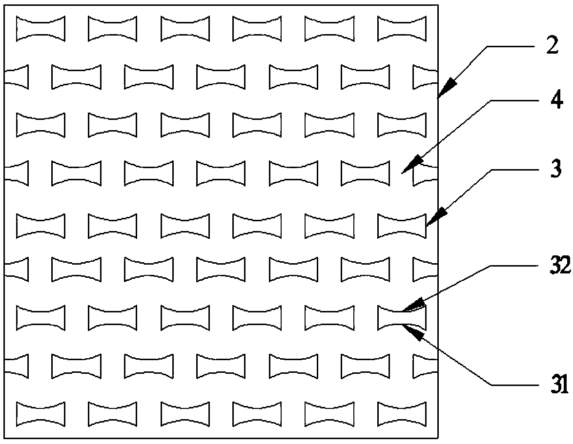
[0029] Such as Figure 1-4 As shown in and 11, a modular concave flame retardant of this embodiment includes more than one single three-dimensional flame retardant channel 1 formed by superimposing two flame retardant sheets 2, and the flame retardant sheet 2 is provided with There is a spoiler column 3, and the spoiler column 3 includes a windward side 31 and a leeward side 32; the windward side 31 of the spoiler column 3 is a concave structure, and the previous row of spoiler columns 3 Located in the front center of the gap 4 between two adjacent spoiler posts 3 in the rear row, and the gap between the two adjacent spoiler posts 3 in the rear row is smaller than the spoiler posts 3 in the previous row width.
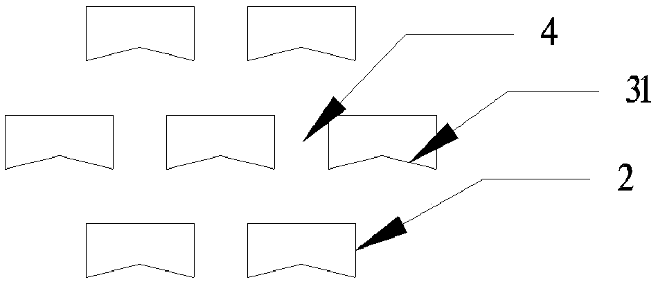
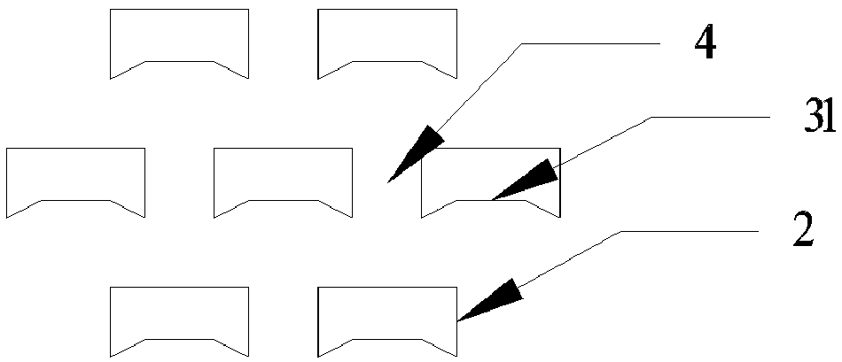
[0030] The concave structure adopts a triangular concave (such as figure 2 shown) or trapezoidal concave (as image 3 shown), or arc concave (such as Figure 4 shown).
[0031] The gap 4 between two adjacent spoiler columns 3 is the flow path of the deflagration ...
Embodiment 2
[0035] Such as figure 1 , as shown in 5-7 and 12, a modular concave flame retardant of this embodiment includes more than one single three-dimensional flame retardant channel 1 formed by superimposing two flame retardant sheets 2, and the flame retardant A spoiler column 3 is provided on the sheet 2, and the spoiler column 3 includes a windward side 31 and a leeward side 32; the leeward side 32 of the spoiler column 3 is a concave structure, and the front row The spoiler post 3 is located in the front center of the gap 4 between two adjacent spoiler posts 3 in the rear row, and the gap between the two adjacent spoiler posts 3 in the rear row is smaller than that of the previous row The width of spoiler column 3.
[0036] The concave structure adopts (such as Figure 5 shown) or trapezoidal concave (as Figure 6 shown) or curved concave (such as Figure 7 shown).
[0037] The gap 4 between two adjacent spoiler columns 3 is the flow path of the deflagration flame.
[0038]...
Embodiment 3
[0041] Such as figure 1 , 8-10 and 11, 12, a modular concave flame retardant of this embodiment includes more than one single three-dimensional flame-retardant channel 1 formed by superimposing two flame-retardant sheets 2, the described The flame-retardant sheet 2 is provided with a spoiler column 3, and the spoiler column 3 includes a windward side 31 and a leeward side 32; the windward side 31 and the leeward side 32 of the spoiler column 3 are both concave structures ; The front row of spoiler posts 3 is located in the front center of the gap 4 between two adjacent spoiler posts 3 in the rear row, and the gap between the two adjacent spoiler posts 3 in the rear row is less than The width of the spoiler columns 3 in the preceding row.
[0042] The concave structure adopts a triangular concave (such as Figure 8 shown) or trapezoidal concave (as Figure 9 shown) or curved concave (such as Figure 10 shown).
[0043] The gap 4 between two adjacent spoiler columns 3 is the ...
PUM
 Abstract
Description
Claims
Application Information
 - R&D
- Intellectual Property
- Life Sciences
- Materials
- Tech Scout
- Unparalleled Data Quality
- Higher Quality Content
- 60% Fewer Hallucinations
Browse by: Latest US Patents, China's latest patents, Technical Efficacy Thesaurus, Application Domain, Technology Topic, Popular Technical Reports.
© 2025 PatSnap. All rights reserved.Legal|Privacy policy|Modern Slavery Act Transparency Statement|Sitemap|About US| Contact US: help@patsnap.com