Door lock device

A door lock and door hook technology, applied in the field of door lock devices, can solve the problems of thick door cover, affecting the overall appearance and cost of home appliances, and achieve the effect of reducing height, beautiful appearance, and avoiding excessive thickness

Pending Publication Date: 2019-03-08
HANGZHOU KAMBAYASHI ELECTRONICS
View PDF0 Cites 0 Cited by
  • Summary
  • Abstract
  • Description
  • Claims
  • Application Information

AI Technical Summary

Problems solved by technology

[0003] The height L of this door lock is relatively large, resulting in a relatively thick door cover, which affects the overall appearance and cost of the home appliance

Method used


Image

  • Door lock device
  • Door lock device
  • Door lock device

Examples


Embodiment 1

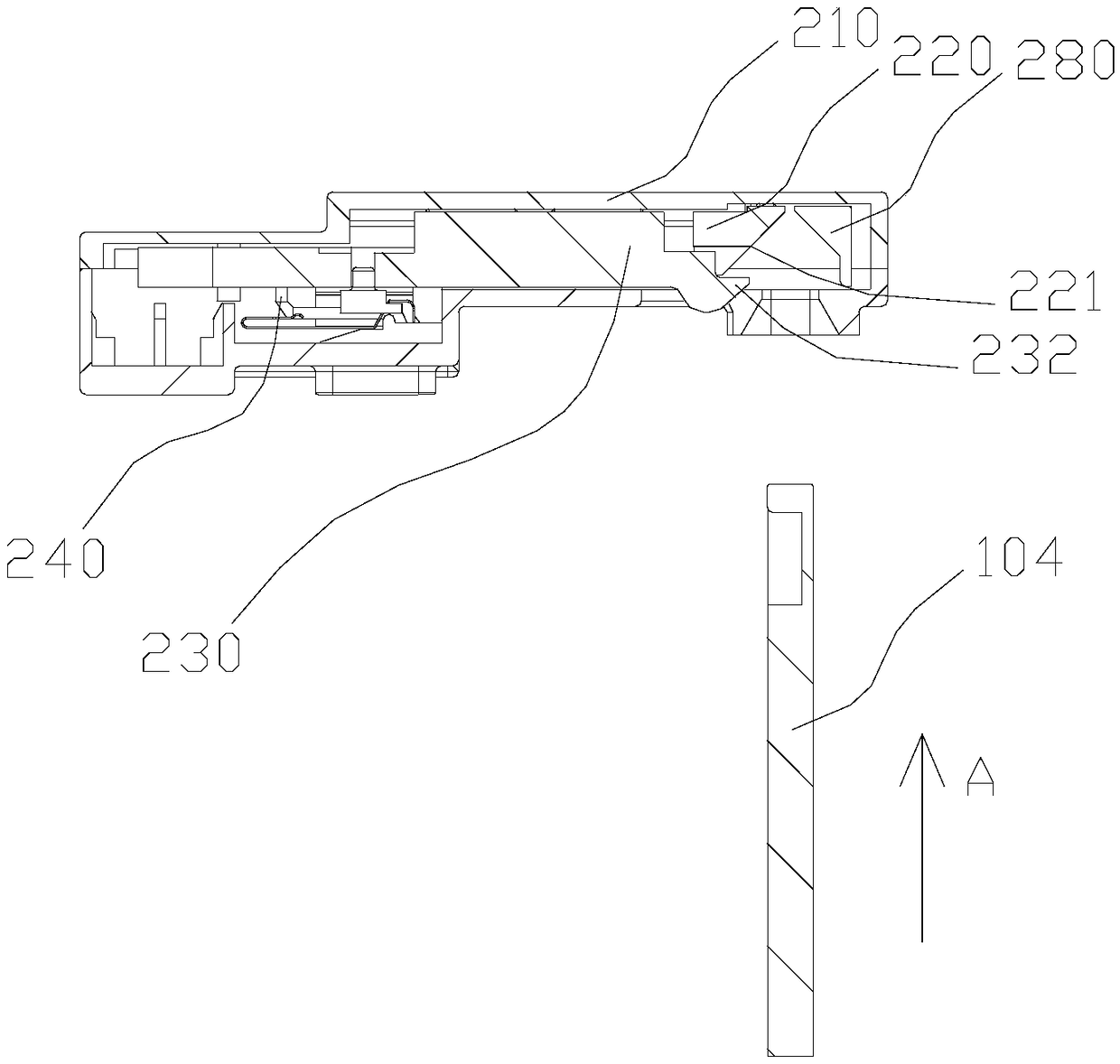
[0025] refer to Figure 2 to Figure 10 , a door lock device of the present invention, comprising a housing 210 and a base body 270, the housing 210 is mounted on the outside of the base body 270. Rod 250, the driving plate 220 and the locking plate 230 are movably connected through the connecting rod 250, under the action of the connecting rod 250, the driving plate 220 can control the movement of the locking plate 230, and the locking plate 230 is provided with a heart-shaped structure 231 and lock tongue 232, one side of the locking plate 230 is provided with a heart-shaped structure 231, the heart-shaped structure 231 is matched with the positioning pin 240, the other side of the locking plate 230 is provided with a lock tongue 232, the The deadbolt 232 cooperates with the door hook 104 . The drive plate 220 is movably mounted on the base body 270, the end of the drive plate 220 is provided with a drive portion 222, and the side wall of the drive portion 222 is provided wi...

Embodiment 2

[0027] refer to Figure 2 to Figure 10 , the difference from the above-mentioned embodiment 1 is that: the connecting rod 250 is hingedly mounted on the base body 270, and the base body 270 is also equipped with an anti-deflection plate 280, and one end of the connecting rod 250 is connected to the driving plate 220, the locking plate 230 is hinged, the other end of the connecting rod 250 is hinged with the deflection plate 280, the deflection plate 280 is provided with an auxiliary deflection part 281, and the side of the auxiliary deflection part 281 close to the drive plate 220 is provided There are bevels.

[0028] Working process of the present invention:

[0029] The working principle of a kind of door lock device of the present invention is:

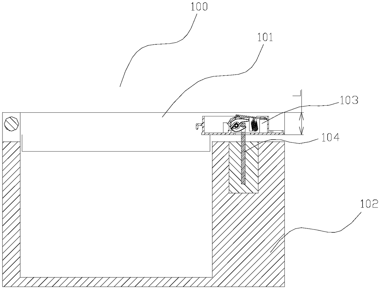
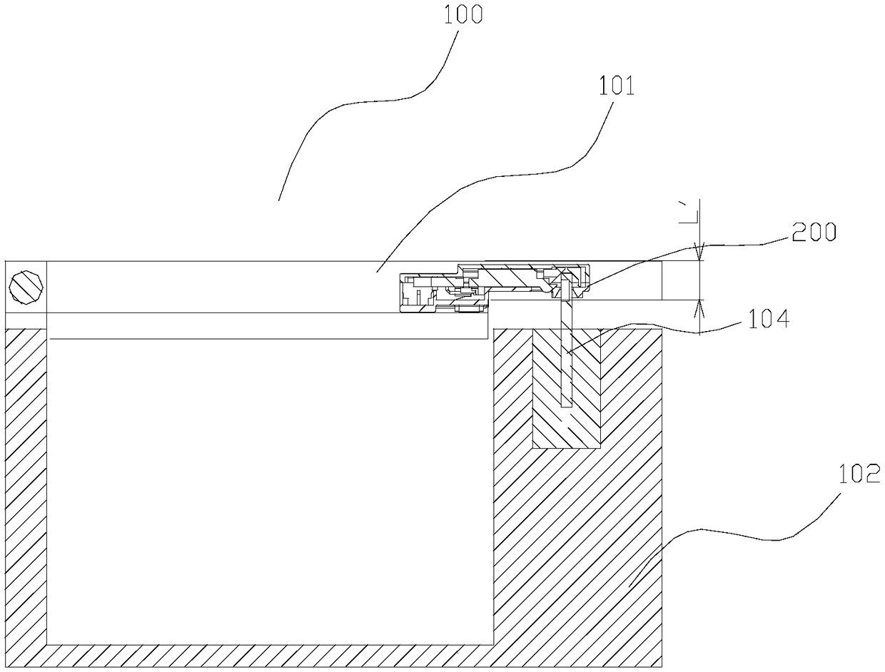
[0030] refer to image 3 , 4 It is intended to install the door lock in the electric appliance before locking the cross-sectional view of the structure. At this time, the heart-shaped structure 231 of the locking plate 230 is ...


PUM


Abstract

The invention provides a door lock device. The door lock device comprises a shell and a base body; and the shell is installed outside the base body. The door lock device is characterized in that a driving plate, a locking plate and a connection rod are arranged in the shell; the driving plate and the locking plate are movably connected through the connection rod; under the effect of the connectionrod, the driving plate can control the locking plate to move; the locking plate is provided with a heart-shaped structure and a spring bolt; the heart-shaped structure is arranged on one side of thelocking plate, and matched with a positioning needle; and the spring bolt is arranged on the other side of the locking plate, and is matched with a door hook. The height of a door lock is effectivelylowered, the problem that an electric appliance door cover is too thick and heavy is solved, and the overall appearance is attractive; the driving plate is controlled to move through the door hook; and under the effects of the connection rod, the locking plate is driven for linkage, the locking plate can be used for locking the door hook, and door locking control is achieved.

Description

【Technical field】 [0001] The invention relates to the technical field of door locks for electrical equipment, in particular to a door lock device. 【Background technique】 [0002] When household appliances are working, the door cover should be locked for safety to prevent accidental opening. figure 1 As shown, the current upper cover type door cover lock structure has a door hook 104 on the door cover, and the door hook 104 cooperates with the existing door lock 103 to realize locking and unlocking actions; there are the following problems: [0003] The height L of this type of door lock is relatively large, resulting in a relatively thick door cover, which affects the overall appearance and cost of the home appliance. [0004] In order to solve the above technical problems, a door lock device with a more optimized structure is needed. 【Content of invention】 [0005] The purpose of the present invention is to solve the problems in the prior art, and propose a door lock de...

Claims


Application Information

Patent Timeline
Patent Type & Authority Applications(China)
IPC IPC(8): E05B65/00E05B63/24E05B15/04E05B15/00
CPCE05B15/00E05B15/04E05B63/24E05B65/00
Inventor 竺建军邓睿何凯
Owner HANGZHOU KAMBAYASHI ELECTRONICS
Why Eureka
Try Eureka