An Electromagnetic Effect Pile End Rigidity Adjusting Device

An adjustment device and electromagnetic effect technology, applied in coatings, infrastructure engineering, anti-corrosion coatings, etc., can solve the problem that the support stiffness cannot be actively intervened and adjusted according to needs, and achieve flexible and convenient control and adjustment, high degree of quantification, and construction The effect of easy operation

Active Publication Date: 2019-10-18
南工天健(厦门)工程技术有限公司
View PDF4 Cites 0 Cited by
  • Summary
  • Abstract
  • Description
  • Claims
  • Application Information

AI Technical Summary

Problems solved by technology

[0004] In view of the deficiencies in the prior art, the purpose of the present invention is to provide an electromagnetic effect pile end stiffness adjustment device, which has stable operation, long service life, and safe operation, and effectively utilizes electromagnetic effects to further improve the existing pile end stiffness adjustment device. Improvement, in order to overcome the shortcomings of the existing pile tip stiffness adjustment device, the support stiffness cannot be actively intervened and adjusted according to needs, and the pile foundation support stiffness can be intervened and adjusted as needed during the entire process of building construction and use, and the control and The adjustment is more flexible and convenient, the implementation is more reliable, the construction operation is simple, the adjustment accuracy is high, and the degree of quantification is high. The anti-corrosion, wear-resistant and anti-aging performance of the inner wall is especially important to prevent the serious wear of the inner wall of the cylinder during the working process

Method used


Image

  • An Electromagnetic Effect Pile End Rigidity Adjusting Device
  • An Electromagnetic Effect Pile End Rigidity Adjusting Device
  • An Electromagnetic Effect Pile End Rigidity Adjusting Device

Examples


Embodiment 1

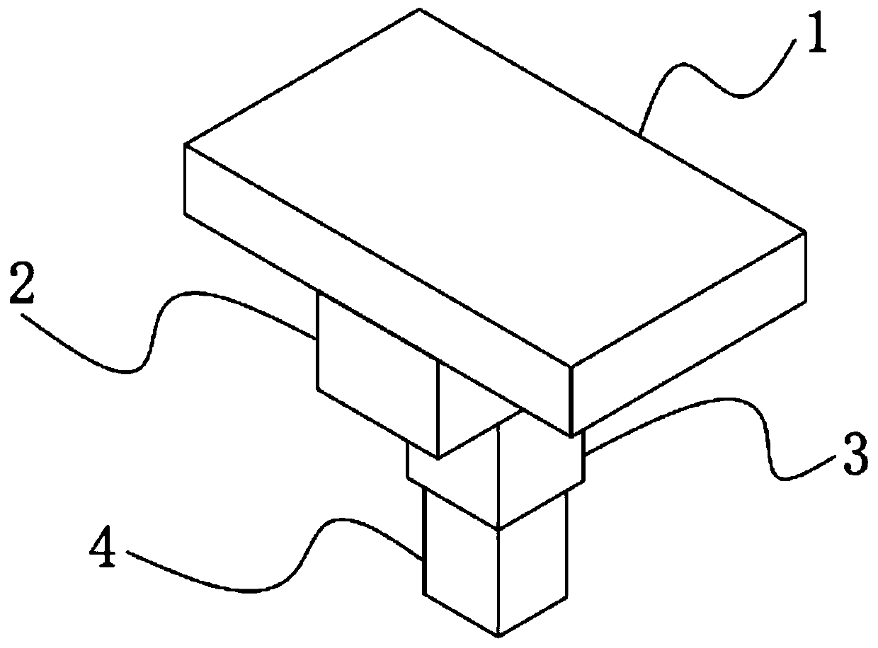
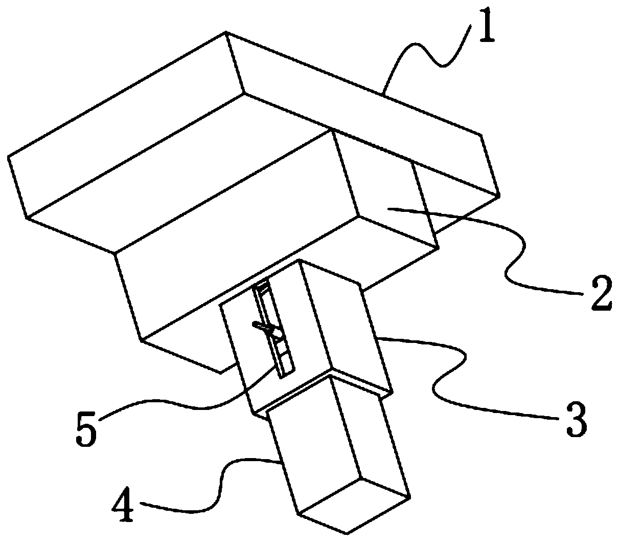
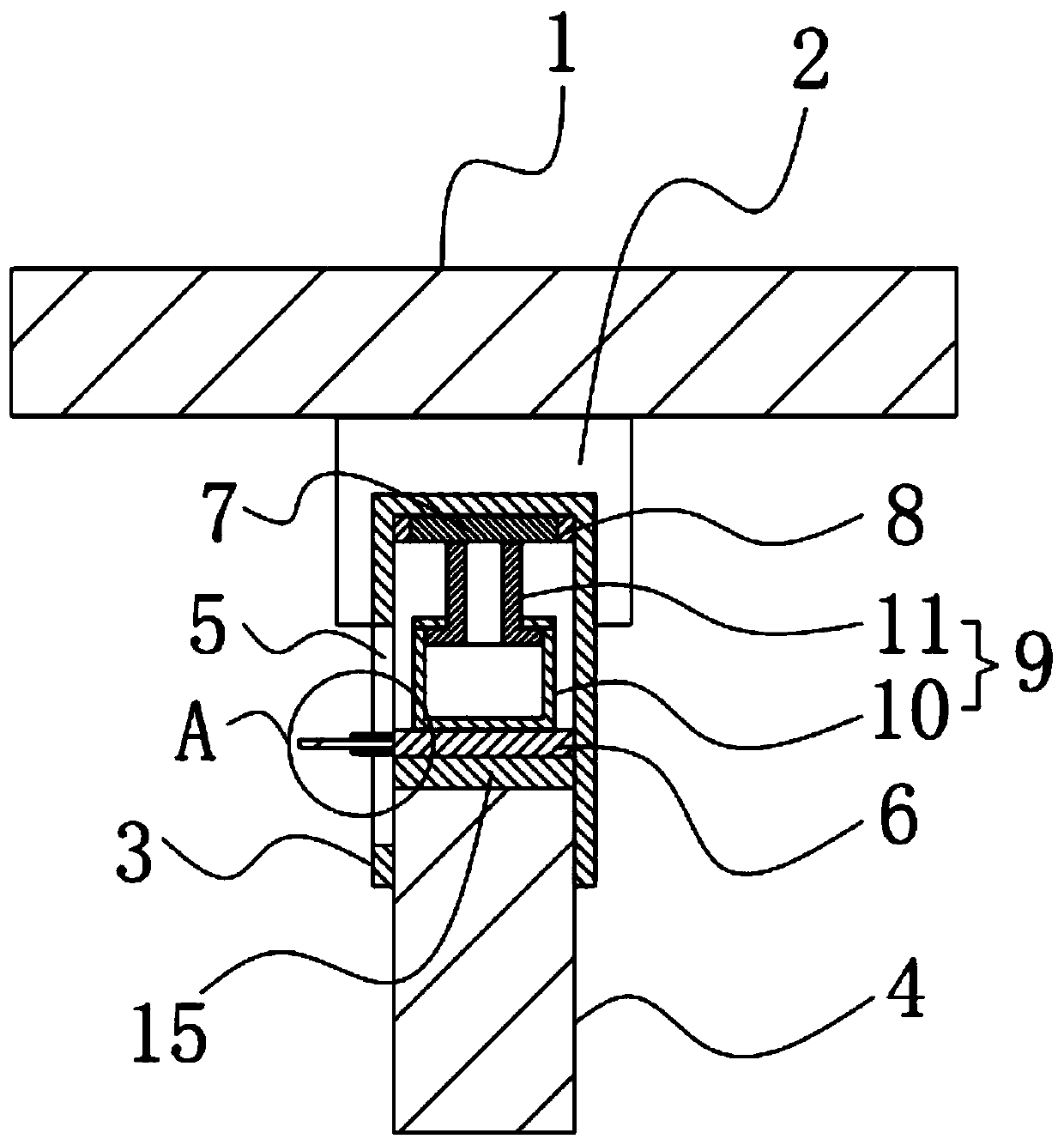
[0050] An electromagnetic effect pile tip stiffness adjustment device, such as Figure 1-6 As shown, it includes a raft 1 and a pile body 4 fixedly installed on the pile foundation. The bottom of the raft 1 is poured with a ground beam 2, and the bottom of the ground beam 2 is reserved with an installation groove 19. The installation groove The inside of 19 is fixedly equipped with a cylinder body 3, the bottom of the cylinder body 3 is an open structure, and the bottom of the inner top wall of the cylinder body 3 is fixedly installed with a permanent magnet 7, and the upper end of the pile body 4 is movably inserted in the The inside of the bottom of the cylinder body 3, and the upper end of the pile body 4 is fixedly installed with a top plate 15, the top of the top plate 15 is fixedly installed with a variable magnet 6, and the variable magnet 6 is located in the cylinder body 3 inside, and a telescopic element 9 is provided between the variable magnet 6 and the permanent m...

Embodiment 2

[0066] The difference from Example 1 is that a protective layer is also provided on the inner wall of the cylinder body 3, and the protective layer is prepared by the following method:

[0067] Take the following raw materials and weigh them by weight: 20 parts of epoxy resin, 8 parts of titanium dioxide powder, 12 parts of phenolic resin, 18 parts of aluminum oxide particles, 10 parts of graphite powder, 11 parts of molybdenum disulfide particles, chromium trioxide particles 10 parts, 2 parts of film-forming aid, 2 parts of accelerator, 1 part of defoamer, 3 parts of leveling agent, 1 part of anti-settling agent and 30 parts of ethanol;

[0068] S1. Add the weighed film-forming aid, accelerator, defoamer, leveling agent, anti-sedimentation agent and ethanol into the mixer and stir for 20min at a stirring speed of 500r / min to prepare a mixed solution;

[0069] S2, adding epoxy resin, calcium carbonate powder, phenolic resin, aluminum oxide particles, graphite powder, molybdenu...

Embodiment 3

[0082] The difference with embodiment 2 is the preparation of protective layer, and its specific preparation method is as follows:

[0083] Take the following raw materials and weigh them by weight: 25 parts of epoxy resin, 10 parts of titanium dioxide powder, 14 parts of phenolic resin, 21 parts of aluminum oxide particles, 11 parts of graphite powder, 12 parts of molybdenum disulfide particles, chromium trioxide particles 11 parts, 3 parts of film-forming aid, 3 parts of accelerator, 2 parts of defoamer, 4 parts of leveling agent, 2 parts of anti-settling agent and 40 parts of ethanol;

[0084] S1. Add the weighed film-forming aid, accelerator, defoamer, leveling agent, anti-sedimentation agent and ethanol into the mixer and stir for 25min at a stirring speed of 600r / min to prepare a mixed solution;

[0085] S2, adding epoxy resin, calcium carbonate powder, phenolic resin, aluminum oxide particles, graphite powder, molybdenum disulfide particles and chromium oxide particles ...


PUM

PropertyMeasurementUnit
thicknessaaaaaaaaaa

Abstract

The invention discloses an electromagnetic effect pile end rigidity adjusting device. The electromagnetic effect pile end rigidity adjusting device comprises a raft plate and a pile body fixedly installed on a pile foundation, and a ground beam is poured at the bottom of the raft plate; a permanent magnet is fixedly installed at the bottom of the inner top wall of a cylinder body, the upper end ofthe pile body is movably inserted into the bottom of the cylinder body, and a top plate is fixedly installed at the end of the upper end of the pile body; and a variable magnet is fixedly installed on the upper portion of the top plate, and a telescopic element is arranged between the variable magnet and the magnet. According to the electromagnetic effect pile end rigidity adjusting device, running is stable, the service life is long, work is safe, the defect that after an existing pile end rigidity adjusting device is arranged, the supporting rigidity can not be actively intervened and adjusted as needed is overcome, control and adjustment are more flexible and convenient, implementation is more reliable, construction operation is easy and convenient, the adjusting precision is high, thequantification degree is high, and a significant promoting effect on promoting development and application of the pile raft foundation full-process active control theory is achieved.

Description

technical field [0001] The invention relates to the technical field of pile raft foundation construction, in particular to an electromagnetic effect pile end stiffness adjusting device. Background technique [0002] With the vigorous promotion of infrastructure construction in our country, pile foundation, an ancient foundation form, has been widely used and developed unprecedentedly. The direct rigid connection between piles and rafts in conventional pile-raft foundations, the overall stiffness is determined by the stiffness of the raft slab and the support stiffness of the pile foundation. If the stiffness of the pile raft needs to be adjusted to meet the requirements of use, the stiffness of the raft can be achieved by adjusting the thickness of the raft, but the cost is often high; the support stiffness of the pile foundation can be adjusted by changing the pile length, pile diameter and pile distance However, the arrangement of piles with different pile diameters and d...

Claims


Application Information

Patent Timeline
Patent Type & Authority Patents(China)
IPC IPC(8): E02D27/01E02D27/12C09D163/00C09D161/06C09D5/08C09D7/48C09D7/61C09D7/63
Inventor 周峰高路恒许勇周泽坤
Owner 南工天健(厦门)工程技术有限公司
Why Eureka
Try Eureka