
Reservoir floating debris cleaning device

A technology for cleaning devices and floating objects, which is applied to the cleaning of open water surfaces, water conservancy projects, buildings, etc., can solve the problems of long residence time, water pollution in the reservoir area, and difficulty in salvage, etc., so as to improve the cleaning effect, improve the cleaning efficiency, and improve the Effects of Stability and Reliability

Active Publication Date: 2021-02-05
浙江景昌建设有限公司
View PDF8 Cites 1 Cited by
  • Summary
  • Abstract
  • Description
  • Claims
  • Application Information

AI Technical Summary

Problems solved by technology

[0002] After the river-type reservoir is impounded, the water body in the reservoir area changes from a river runoff with a fast flow rate and a large flow rate to a river-type reservoir with a slow flow rate, a long residence time, a large backwater area, and many bays and forks. The slow water surface retention and accumulation in front of the dam, at the junction of main and branch streams, backwaters, port areas, and some tassels will directly affect the normal and safe operation of the reservoir, leading to water quality pollution and ecological landscape impacts in the reservoir area, and will have a negative impact on the safety of shipping in the reservoir area. threaten
[0003] In the prior art, manual cleaning is generally used when dealing with floating objects in reservoirs. Not only is the efficiency low, but also due to the different densities of the floating objects, the floating objects do not completely float on the water surface. easy to pollute the reservoir

Method used


Image

  • Reservoir floating debris cleaning device
  • Reservoir floating debris cleaning device
  • Reservoir floating debris cleaning device

Examples


Embodiment Construction

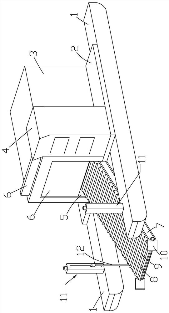
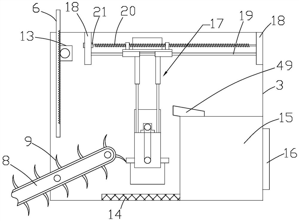
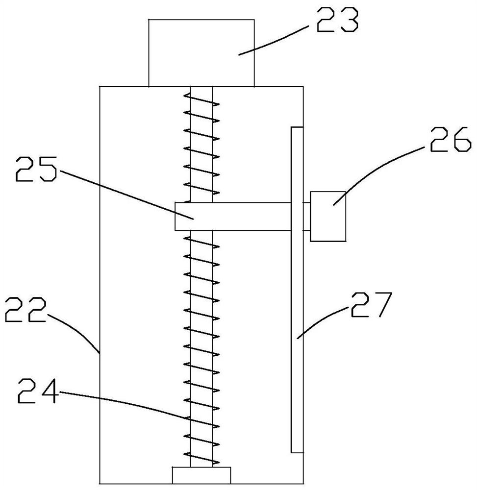
[0028] like Figure 1 to Figure 5 As shown, it is a kind of reservoir floating debris cleaning device of the present invention, comprising two hulls 1, the top surfaces of the two hulls 1 are connected by a deck 2, a cockpit 4 is arranged on the deck 2, and a cleaning device Mechanism and floating object cleaning box 3, the cleaning mechanism includes a support plate 7, the support plate 7 is rotatably connected to the floating cleaning box, the angle between the support plate 7 and the horizontal direction is 0°~60°, and the two ends of the support plate 7 are respectively set There are a driving wheel and a driven wheel, the driving wheel is located on the side near the floating debris cleaning box 3, the driving wheel is connected with a transmission motor, the transmission motor is located in the support plate 7, the driving wheel and the driven wheel are connected by a conveyor belt 8, and the conveyor belt 8 Carrier roller 51 is evenly arranged between support plate 7, a...


PUM


Abstract

The invention discloses a floating object cleaning device in a reservoir, which comprises two hulls, the top surfaces of the two hulls are connected through a deck, and a cleaning mechanism and a floating object cleaning box are arranged on the deck, and the cleaning mechanism is located between the two hulls , and the cleaning mechanism is connected to the hull through the lifting mechanism. The end of the cleaning mechanism extends into the inside of the floating object cleaning box through the feed port. The floating object cleaning box is equipped with a solid-liquid separation mechanism and a storage tank. The moving mechanism is connected in the floating object cleaning box, the bottom of the floating object cleaning box is provided with a water-permeable tank, one side of the water-permeable tank is provided with a storage box, and the top surface of the storage box is provided with a guide groove. The invention can continuously transport the floating objects in the reservoir to the floating object cleaning box, reduce the intensity of manual salvage, facilitate the cleaning of floating objects of different depths in the reservoir, greatly improve the cleaning efficiency of the floating objects in the reservoir, and expand the capacity of the cleaning device. The scope of work.

Description

technical field [0001] The invention relates to a device for cleaning floating objects in a reservoir. Background technique [0002] After the river-type reservoir is impounded, the water body in the reservoir area changes from a river runoff with a fast flow rate and a large flow rate to a river-type reservoir with a slow flow rate, a long residence time, a large backwater area, and many bays and forks. The slow water surface retention and accumulation in front of the dam, at the junction of main and branch streams, backwaters, port areas, and some tassels will directly affect the normal and safe operation of the reservoir, leading to water quality pollution and ecological landscape impacts in the reservoir area, and will have a negative impact on the safety of shipping in the reservoir area. threaten. [0003] In the prior art, manual cleaning is generally used when dealing with floating objects in reservoirs. Not only is the efficiency low, but also due to the different ...

Claims


Application Information

Patent Timeline
Patent Type & Authority Patents(China)
IPC IPC(8): E02B15/10
CPCE02B15/10
Inventor 许育锋刘学应林建青何方严密张玮
Owner 浙江景昌建设有限公司
Learn More