
Automobile automatic fire extinguishing system

An automatic fire extinguishing system and automobile technology, which is applied in fire rescue and other fields, can solve the problems of easy loosening and falling off of fire extinguishers, damaged insulating rubber, unstable performance, etc., and achieves simple and easy installation, slow burning speed of large fires, small and compact shape Effect

Inactive Publication Date: 2019-03-08
蒋承革
View PDF10 Cites 3 Cited by
  • Summary
  • Abstract
  • Description
  • Claims
  • Application Information

AI Technical Summary

Problems solved by technology

A large part of spontaneous combustion accidents are fires in the engine compartment, and this is caused by short-circuit fires caused by aging circuits or damaged insulation rubber, false joints, etc. Since the lines are not exposed on the surface of the car body, most of the lines are distributed in the machine cover Therefore, many drivers neglect to check and maintain it
The oil circuit is as important and terrible as the hidden danger of the circuit in the cause of spontaneous combustion accidents. Because some oil leakage in the engine room has not been discovered in time, the temperature in the engine room rises sharply in the high temperature environment in summer, which is enough to ignite the leaked oil and cause spontaneous combustion. risk
[0003] Due to the compact internal structure and narrow space of the car, and the large volume of the existing car fire extinguishing system, it is difficult to install; the vibration is large when the car is running, and the existing car fire extinguishing system is easy to loose and fall off due to car vibration, and the performance is unstable.

Method used


Image

  • Automobile automatic fire extinguishing system
  • Automobile automatic fire extinguishing system
  • Automobile automatic fire extinguishing system

Examples


Embodiment Construction

[0027] The present invention will be further described below in conjunction with the accompanying drawings and embodiments. It should be noted that the specific embodiments of the present invention are only for the purpose of describing the technical solution more clearly, but not as a limitation of the protection scope of the present invention.

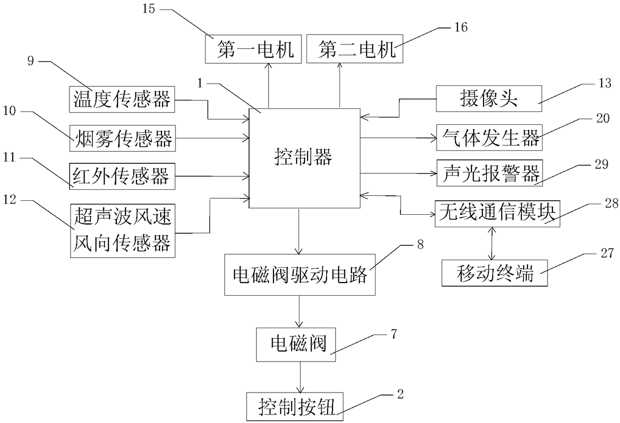
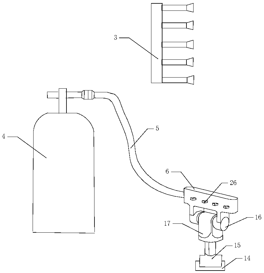
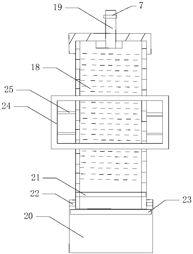
[0028] see Figure 1-3 , an automobile automatic fire extinguishing system, comprising a controller 1, a control button 2 and several fire extinguishing assemblies, the controller 1 and the control button 2 are arranged in the cab, and the fire extinguishing assemblies are respectively arranged at a plurality of fire positions to be detected inside the car body , the fire extinguishing assembly includes a fire detection sensor 3, a fire extinguisher 4, a metal pipe 5 and a nozzle 6, the fire detection sensor 3 is electrically connected to the controller 1, and the fire detection sensor 3 is used to generate an alarm signal from the c...


PUM


Abstract

The invention belongs to the technical field of fire fighting systems, and relates to an automobile automatic fire extinguishing system. The automobile automatic fire extinguishing system comprises acontroller, control buttons and a plurality of fire extinguishing assemblies. The fire extinguishing assemblies are separately arranged at a plurality of fire positions to be detected inside an automobile body, and the fire extinguishing assemblies include fire detection sensors, fire extinguishers, metal tubes and sprinklers. The fire detection sensors are electrically connected with the controller, the fire detection sensors are used for generating an alarm signal from the collected fire condition information inside the automobile body and send the alarm signal to the controller, and the controller is used for controlling the fire extinguishers to work according to the received fire condition information. The fire extinguishers are connected with the sprinklers through the metal tubes, and solenoid valves are arranged at jet ports of the fire extinguishers. The controller drives the solenoid valves through solenoid valve drive circuits, and the control buttons are used for controlling starting and stopping of the solenoid valves. The automobile automatic fire extinguishing system has simple structure design, high fire extinguishing speed and stable performance, and can automatically detect a fire inflammable point in the automobile and automatically extinguish the fire.

Description

technical field [0001] The invention belongs to the technical field of fire-fighting systems, and in particular relates to an automatic fire-extinguishing system for automobiles. Background technique [0002] Fire extinguishers are a very common vehicle-mounted facility. When a vehicle catches fire due to collision or spontaneous combustion during driving, it is necessary to use a fire extinguisher. However, most of the fire extinguishers used in existing vehicles are hand-held fire extinguishers, so it is not practical for daily use. Most of the fire extinguishers are left idle in the trunk of the car. When the vehicle catches fire, the driver needs to get out of the car, open the trunk, take out the fire extinguisher, and then put out the fire. At this time, the fire has already expanded, and if the fire is not extinguished in time, it will easily lead to the scrapping of the entire vehicle. Therefore, after the damage, you can only be responsible for yourself, which has b...

Claims


Application Information

Patent Timeline
IPC IPC(8): A62C3/07A62C31/02A62C37/38
CPCA62C3/07A62C31/02A62C37/38
Inventor 蒋承革
Owner 蒋承革
Learn More