
Tank valve

A storage tank and valve body technology, which is applied in the application field of storage tank valves, can solve the problems of high manufacturing cost, reforming drilling tools, increasing storage tank valve configuration time and manufacturing cost, etc.

Active Publication Date: 2019-03-01
CELLCENTRIC GMBH & CO KG
View PDF8 Cites 1 Cited by
  • Summary
  • Abstract
  • Description
  • Claims
  • Application Information

AI Technical Summary

Problems solved by technology

The manufacturing cost of this structure is relatively high, due to the fact that when drilling the pipe elements into the substrate, feeding different pipe elements with different diameters requires the respective reformation of the drilling tool
This increases configuration time and manufacturing costs for tank valves
This disadvantage is especially noticeable when used in vehicles

Method used


Image

  • Tank valve
  • Tank valve
  • Tank valve

Examples


Embodiment Construction

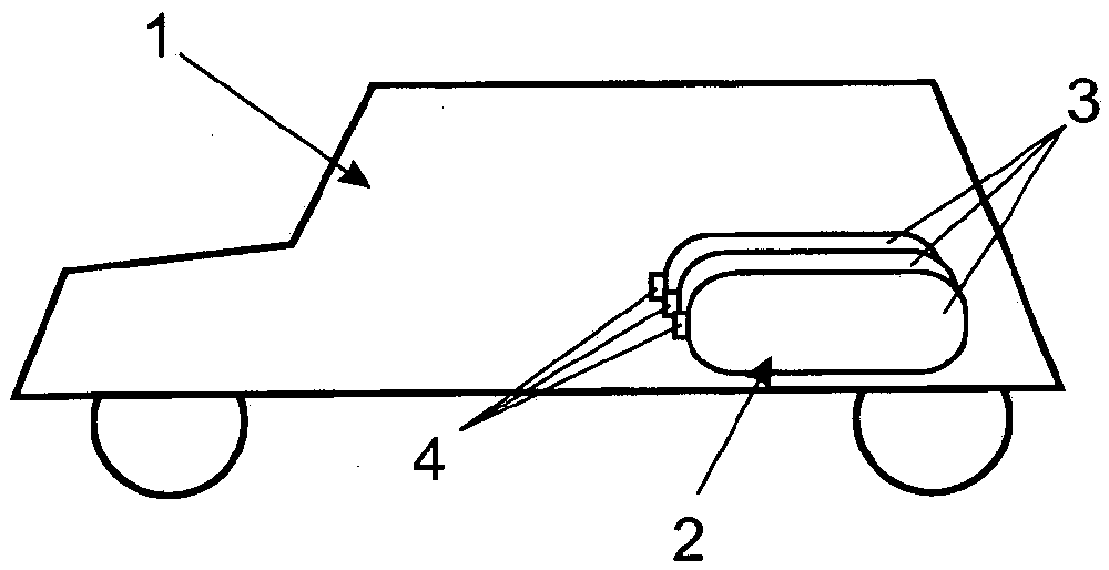
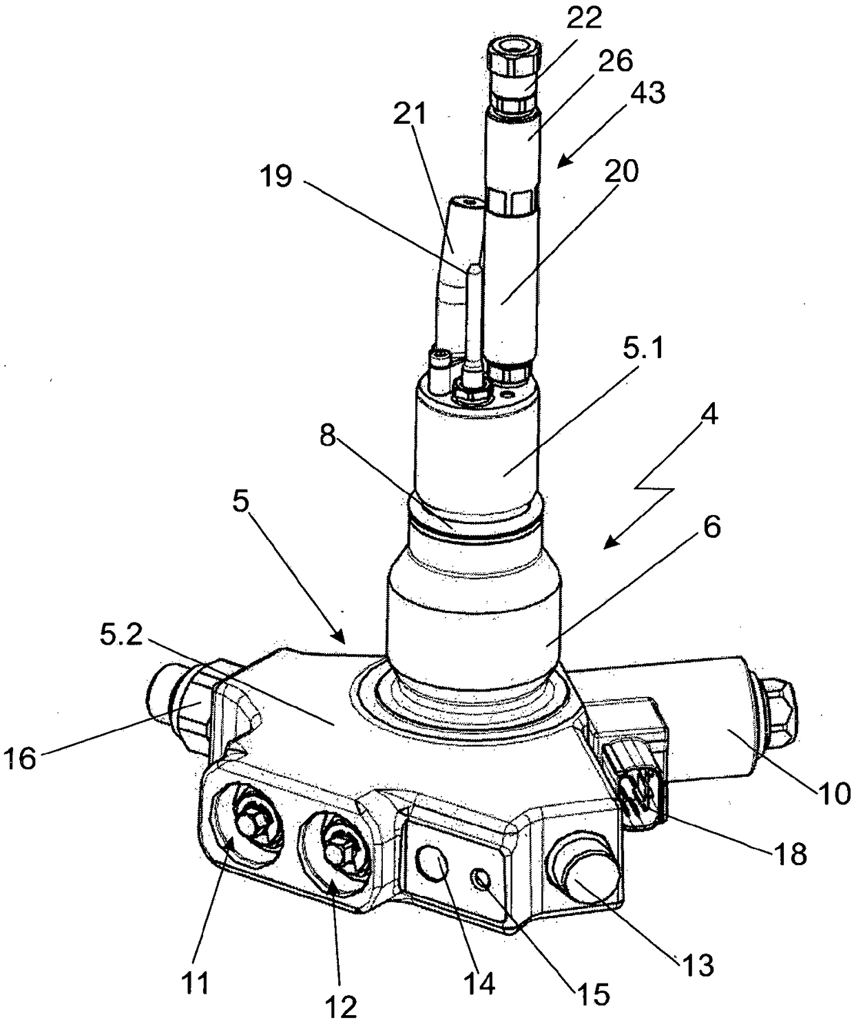
[0030] figure 1 The vehicle 1 is shown purely by way of example. This vehicle is powered by gaseous fuels such as compressed natural gas or compressed hydrogen. For this purpose, the fuel can be converted into power for the drive in the internal combustion engine or, especially when hydrogen is used, preferably also in the fuel cell system. In order to store compressed gas, there is a storage device designated as a whole with 2 in the vehicle 1 . This storage device consists of several individual compressed gas containers 3 each having a tank valve 4 . The storage tank valve 4 is also called On-Tank-Valve, or OTV for short. Therein, the individual compressed gas containers 3 together with their storage tank valves 4 can be connected to one another, for example in a manner known from the aforementioned prior art, via common pipes in order to be able to use the gas from the storage device 2 in the vehicle. The nominal pressure of such a compressed gas container 3 with storag...


PUM


Abstract

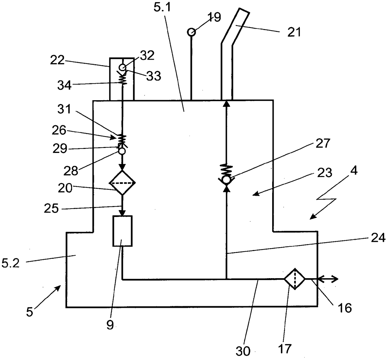
The invention relates to a tank valve (4) for mounting on a compressed gas tank (3), comprising a main body (5), further comprising a common gas port (16) for filling the tank / removing gas from the tank, said gas port (16) branching, within the main body (5), into a filling line (24) and a removal line (25) as part of a removal path, and comprising a removal valve (9) in the removal line (25). Thetank valve of the invention is characterized in that a non-return valve (26) that prevents any flow against the direction of flow (A) during the removal of gas is arranged in series to the removal valve (9) in the removal path.

Description

technical field [0001] The invention relates to a tank valve of the type defined in detail in the preamble of claim 1 . The invention also relates to the use of such tank valves. Background technique [0002] Tank valves that can be mounted on compressed gas containers are known from the general prior art. The English name of such a storage tank valve is On-Tank-Valve, or OTV for short. Wherein, the storage tank valve is a structure comprising a base body, which has at least two parts, wherein the first base body part protrudes into the compressed gas container and is closely connected with it when the installation is completed. This first base part is usually screwed via an external thread into the internal thread of a corresponding socket of the compressed gas container. In addition to this first base body part, which is inside the compressed gas container or its connection thread when it is installed, the base body usually also has a second base body part, which is out...

Claims


Application Information

Patent Timeline
Patent Type & Authority Applications(China)
IPC IPC(8): F17C13/04
CPCF17C2201/0109F17C2201/056F17C2201/058F17C2205/0134F17C2205/0317F17C2205/0326F17C2205/0329F17C2205/0332F17C2205/0335F17C2205/0341F17C2205/035F17C2205/0385F17C2205/0391F17C2205/0394F17C2221/012F17C2221/033F17C2223/0123F17C2223/036F17C2225/045F17C2250/0439F17C2260/012F17C2260/018F17C2260/042F17C2265/066F17C2270/0178F17C2270/0184F17C13/04Y02E60/32
Inventor S·艾伯特F·高尔P·豪斯曼
Owner CELLCENTRIC GMBH & CO KG
Learn More