
Quantum-level cascaded laser with vertical cavity surface emission function

A vertical cavity surface emission, quantum cascade technology, applied in the direction of lasers, laser components, semiconductor lasers, etc., can solve the problems of reducing the threshold current density of devices, increasing the difficulty of material growth, unfavorable device heat dissipation, etc., to increase non-radiation Effects of attenuation lifetime, lower device threshold, and shortened device cavity length

Inactive Publication Date: 2019-03-01
INST OF SEMICONDUCTORS - CHINESE ACAD OF SCI
View PDF3 Cites 2 Cited by
  • Summary
  • Abstract
  • Description
  • Claims
  • Application Information

AI Technical Summary

Problems solved by technology

However, in order to achieve lasing, the surface emitting device must overcome the additional loss caused by the first-order scattering of the second-level grating, which is not conducive to reducing the threshold current density of the device.
At the same time, for a shorter vertical cavity structure, a cavity surface reflectivity as high as 99% is required, usually relying on a multi-layer DBR structure, and more DBR layers will make the device have higher resistance and greater light absorption, affecting the device performance
In addition, the DBR layer matching the InP substrate has InGaAlAs / InAlAs pairs. Since the refractive index difference between the two materials is small, 40-50 pairs need to be grown in order to achieve a reflectivity of more than 99%. On the one hand, the growth rate of the material is increased. On the other hand, such a thick thickness is not conducive to heat dissipation of the device, so the material selection of the DBR layer is also open to question

Method used


Image

  • Quantum-level cascaded laser with vertical cavity surface emission function
  • Quantum-level cascaded laser with vertical cavity surface emission function

Examples


Embodiment Construction

[0028] In order to make the object, technical solution and advantages of the present invention clearer, the present invention will be further described in detail below in conjunction with specific embodiments and with reference to the accompanying drawings.

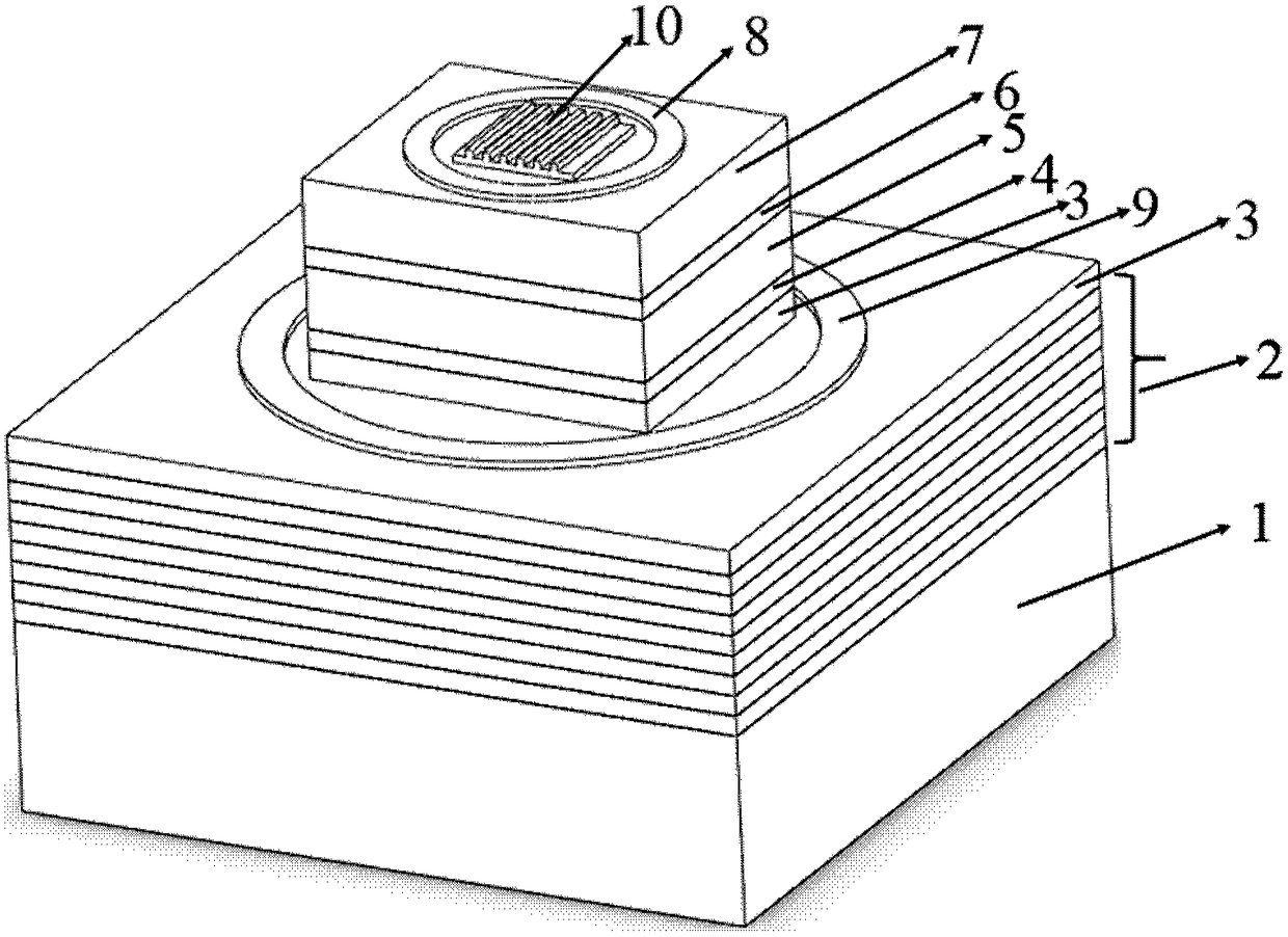
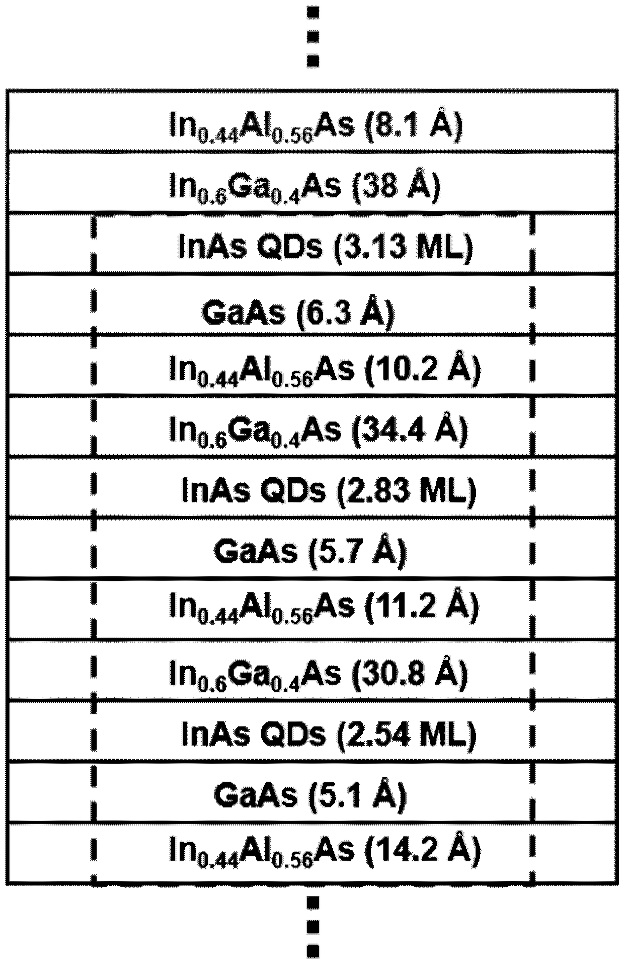
[0029] An embodiment of the present invention provides a vertical cavity surface emitting quantum cascade laser, please refer to figure 1 ,include:

[0030] Quantum dot active region layer, inserting quantum dot intercalation in each cycle of the active region of the laser to form a quantum dot active region layer;

[0031] In this embodiment, by inserting two or more layers of quantum dot intercalation in each period of the active region of the laser, the free movement of electrons parallel to the plane of the quantum well is restricted, so that the originally continuous subbands become truly energy isolated. The inserted quantum dot state is used as the final state of the electronic radiation transition, breaking the t...


PUM


Abstract

The invention discloses a quantum-level cascaded laser with a vertical cavity surface emission function. The quantum-level cascaded laser comprises a quantum dot active area layer, a distribution Bragg reflector layer and a grating layer, wherein the quantum dot active area layer is formed by inserting a quantum dot insertion layer in each period of an active area of the laser; and the distribution Bragg reflector layer is combined with the grating layer to form a vertical resonant cavity so as to realize surface emission. According to the laser, quantum dot insertion layers are introduced atproper positions in the active area layer, and a quantum dot state serves as a final state of electronic radiative transition, so that a radiation mode of the device has an electric field component vertical to a quantum well plane and then a traditional vertical cavity surface emission laser can be prepared. The laser is capable of improving the power and conversion efficiency of the device and reducing the threshold current on one hand, and is capable of remarkably reducing the size of the device and decreasing the threshold current on the other hand.

Description

technical field [0001] The invention relates to the technical field of infrared semiconductor optoelectronic devices, in particular to a vertical cavity surface emitting quantum cascade laser structure. Background technique [0002] Compared with ordinary semiconductor lasers with inter-band recombination light emission mechanism, quantum cascade lasers are based on sub-band transitions, so they have the advantages of adjustable energy bands and wide wavelength coverage; in gas detection, medical diagnosis, high-resolution It has very broad application prospects in fields such as spectroscopy, but its biggest defect is high threshold power consumption and low power conversion efficiency. However, in some portable applications, quantum cascade lasers are often required to have small volume and low power consumption to facilitate system miniaturization and integration. At present, the ways to obtain low-power quantum cascade lasers mainly include: appropriately reducing the d...

Claims


Application Information

Patent Timeline
IPC IPC(8): H01S5/183H01S5/343
CPCH01S5/18361H01S5/3432H01S5/34366
Inventor 程凤敏张锦川王东博赵越刘峰奇卓宁王利军刘俊岐刘舒曼王占国
Owner INST OF SEMICONDUCTORS - CHINESE ACAD OF SCI
Learn More