Fuse Structure and Fuses

A technology of fusing and fusing parts, applied in emergency protection devices, circuits, electrical components, etc., can solve the problems of unfavorable electrical safety and personal safety, difficult to break overload current, slow fusing speed, etc., and achieve safe and fast fusing, and arc burning time Short, the effect of improving the structural strength

Active Publication Date: 2020-03-31
BYD CO LTD
View PDF6 Cites 0 Cited by
  • Summary
  • Abstract
  • Description
  • Claims
  • Application Information

AI Technical Summary

Problems solved by technology

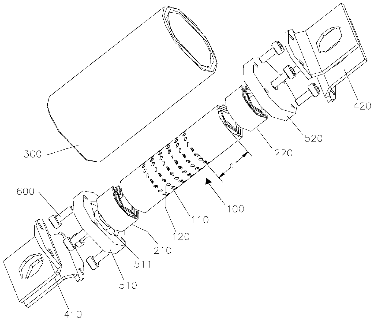
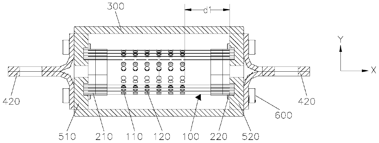
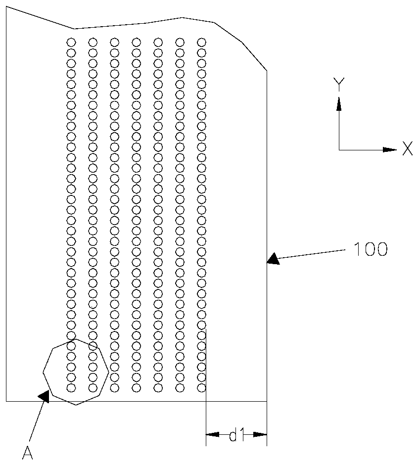
[0004] Based on this, the present invention provides a fusing structure and a fuse, aiming at solving the problem that the existing fusing structure has a long arcing time and a slow fusing speed when it is blown under an overcurrent, and it is difficult to break the overload current, which is not conducive to the connected circuit. Other electrical safety and personal safety technical issues

Method used


Image

  • Fuse Structure and Fuses
  • Fuse Structure and Fuses
  • Fuse Structure and Fuses

Examples


Embodiment Construction

[0026] In order to make the technical problems, technical solutions and beneficial effects to be solved by the present invention clearer, the present invention will be further described in detail below in conjunction with the accompanying drawings and embodiments. It should be understood that the specific embodiments described here are only used to explain the present invention, not to limit the present invention.

[0027] It should be noted that when an element is referred to as being “fixed” or “disposed on” another element, it may be directly on the other element or there may be an intervening element at the same time. When an element is referred to as being "connected to" another element, it can be directly connected to the other element or intervening elements may also be present.

[0028] It should also be noted that the orientation terms such as up and down in the following embodiments are only relative concepts or refer to the normal use state of the product, and shoul...


PUM


Abstract

A fuse structure comprises a fuse element. The fuse element is a multi-layer structure made by rolling or folding an overcurrent protection membrane (100). A gap (101) is arranged between layers of the multi-layer structure. An insulating material (102) is filled in the gap (101).

Description

technical field [0001] The invention relates to the technical field of circuit protection, in particular to a fusing structure and a fuse. Background technique [0002] As a protective device, fuses are often used to protect electronic components or electrical equipment in circuits. When the instantaneous current in the circuit exceeds the predetermined current rating, the fusing structure in the fuse will be melted at high temperature due to the heat generated by the excessive current, and then an open circuit will be formed, so that the overcurrent will no longer flow into the circuit. Protect circuits and electrical equipment from damage. [0003] Existing fuses, especially fuses with higher current and voltage ratings, basically use thicker sheet fuse structures. The applicant found in long-term production and application that the existing fusing structure has long arcing time and slow fusing speed when it is blown under overcurrent, and it is difficult to break the ov...

Claims


Application Information

Patent Timeline
Patent Type & Authority Patents(China)
IPC IPC(8): H01H85/08H01H85/143
CPCH01H85/08H01H85/143H01H85/12
Inventor 徐芸湘郑雷刘子岳
Owner BYD CO LTD
Why Eureka
Try Eureka