
Physical buoyancy experimental device facilitated students to understand and remember

An experimental device and memory technology, applied in teaching models, educational appliances, instruments, etc., can solve problems such as inconvenient control of the height of objects, water splashing, and inability to achieve memory effects, and achieve easy understanding and memory, and improve progress. Effect

Inactive Publication Date: 2019-03-01
刘美伊
View PDF5 Cites 1 Cited by
  • Summary
  • Abstract
  • Description
  • Claims
  • Application Information

AI Technical Summary

Problems solved by technology

[0004] 1. Although the existing mechanics teaching has real objects as a reference, it takes a long time to change one force experiment process to another force experiment process, resulting in students being unable to form a specific scene in their minds and failing to achieve a good memory effect , reducing the effect of class;
[0005] 2. When measuring the physical buoyancy on the spring gauge, the object is generally introduced into the solution by means of a support frame and a hand-held method, but these two methods make it inconvenient to control the height of the object, and it is not convenient to ensure the spring force gauge. Whether it is in a vertical state, which affects the measurement of object buoyancy;
[0006] 3. In the experimental process of the drainage method, the water discharged from the beaker is generally collected in the form of an external measuring cup, but this method needs to adjust the position of the measuring cup and the beaker, and there may be water splashing during the drainage process. Give the experiment cause inconvenience

Method used


Image

  • Physical buoyancy experimental device facilitated students to understand and remember
  • Physical buoyancy experimental device facilitated students to understand and remember
  • Physical buoyancy experimental device facilitated students to understand and remember

Examples


Embodiment

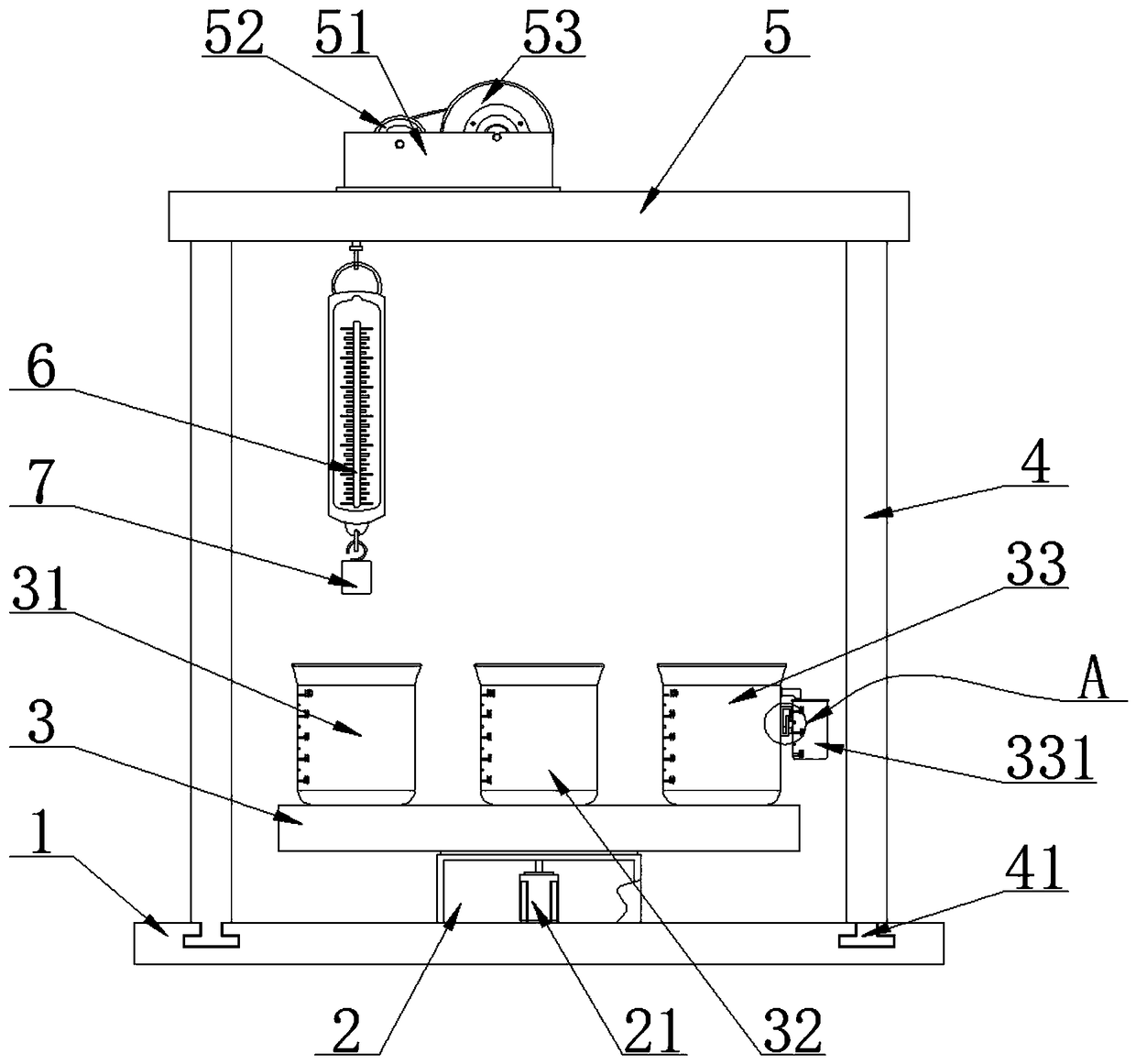
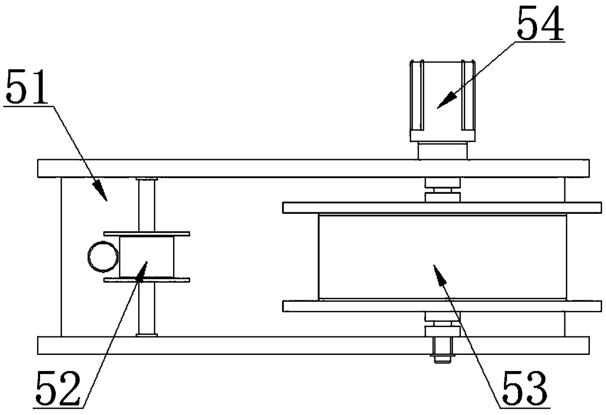
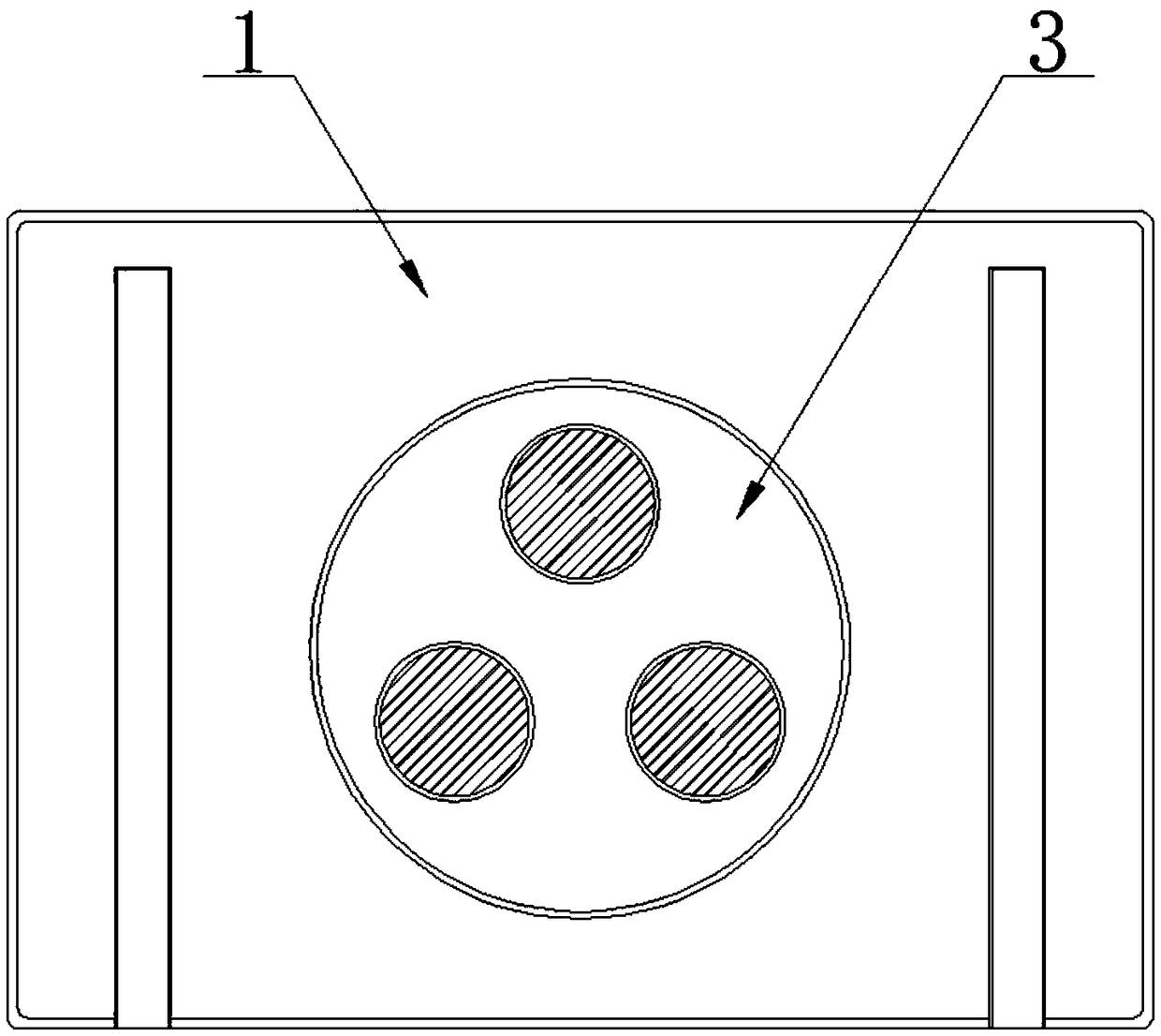
[0033] see Figure 1-9 , the present invention provides a technical solution: a physical buoyancy experimental device that helps students understand and remember, including a base 1, a support frame 4 and a top seat 5, the top of the base 1 is slidably connected to the support frame 4, The top of the support frame 4 is fixed with the top seat 5, and the top of the top seat 5 is connected with a wire take-up housing 51 by means of bolts, and the inner side wall of the wire take-up housing 51 is rotatably connected with a take-up reel 53 and the guide plate 52, the outer wall of the wire take-up housing 51 is connected with a motor b54 close to the end of the take-up reel 53, the output shaft of the motor b54 is connected to the take-up reel 53 in rotation, and the motor b54 is connected to the external power supply Electrically connected, the outer wall of the take-up reel 53 is wound with a rope, one end of the rope is fixed to the take-up reel 53, and the other end is connect...


PUM


Abstract

The invention belongs to the technical field of buoyancy experimental devices, and particularly relates to a physical buoyancy experimental device facilitated students to understand and remember. Thephysical buoyancy experimental device includes a base, a supporting frame and a top seat, the top of the base is slidably connected with the supporting frame, and the top seat is fixed to the top of the supporting frame. When doing a buoyancy experiment, a teacher can generally demonstrate four processes to the students, and the first process refers to detect whether buoyancy is related to the density of displaced liquid or not; the second process refers to detect whether the buoyancy is related to the volume of an object immersed in the liquid or not; the third process refers to explore the relationship between the magnitude of the buoyancy and the magnitude of gravity acting on the displaced liquid, and the third process is usually proved by two different experimental methods; and experimental demonstration of these three processes takes a long time, after the experiment in the first process is completed, work of a motor a drives a placement plate to rotate to make a beaker b rotateto the lower part of a measuring block, so as to facilitate the teacher to carry out operation of the experiment in the second process.

Description

technical field [0001] The invention belongs to the technical field of buoyancy experiment devices, and in particular relates to a physical buoyancy experiment device which is helpful for students to understand and memorize. Background technique [0002] Force refers to the difference (resultant force) between the pressure of the fluid (liquid and gas) on each surface of an object in a fluid (including liquid and gas). In 245 BC, Archimedes discovered the principle of buoyancy. The definition of buoyancy is F buoyancy = G row (that is, the buoyancy of the object is equal to the gravity of the liquid displaced when the object sinks), which can be used for calculation to derive the formula F float = ρ liquid gV row. Physics teaching often involves various aspects of mechanics. Teachers often make various Various teaching aids are used to calculate the gravity of the liquid removed by the object. The teaching aids generally include weights, beakers, water receiving containers a...

Claims


Application Information

Patent Timeline
IPC IPC(8): G09B23/12
CPCG09B23/12
Inventor 刘美伊
Owner 刘美伊
Learn More