
Cold end of low-temperature high-pressure plunger pump

A low-temperature high-pressure, plunger pump technology, applied in pumps, pump components, variable capacity pump components, etc., can solve the problem that ordinary materials do not have low-temperature use characteristics, cannot meet low-temperature high-pressure pumping of liquid nitrogen, and are unfavorable for low-temperature high-pressure pumping. and other problems, to achieve the effect of high output pressure, ensure reliability, and improve pumping capacity

Inactive Publication Date: 2019-03-01
YANTAI JEREH PETROLEUM EQUIP & TECH CO LTD
View PDF5 Cites 111 Cited by
  • Summary
  • Abstract
  • Description
  • Claims
  • Application Information

AI Technical Summary

Problems solved by technology

However, other fracturing pumps cannot meet the low-temperature and high-pressure pumping of liquid nitrogen as a special medium in terms of structure, sealing and materials. Directly generate heat exchange with the outside world, thereby vaporizing liquid nitrogen; 2. Ordinary materials do not have low-temperature use characteristics, and will fail under low-temperature operations; 3. There is no sealing ring support between the plunger and the cylinder of the fracturing pump, and the high-speed movement Due to the large friction surface, it is not only easy to generate more heat, but also the plunger is prone to eccentricity during movement, which is not conducive to low temperature and high pressure pumping

Method used


Image

  • Cold end of low-temperature high-pressure plunger pump

Examples


Embodiment 1

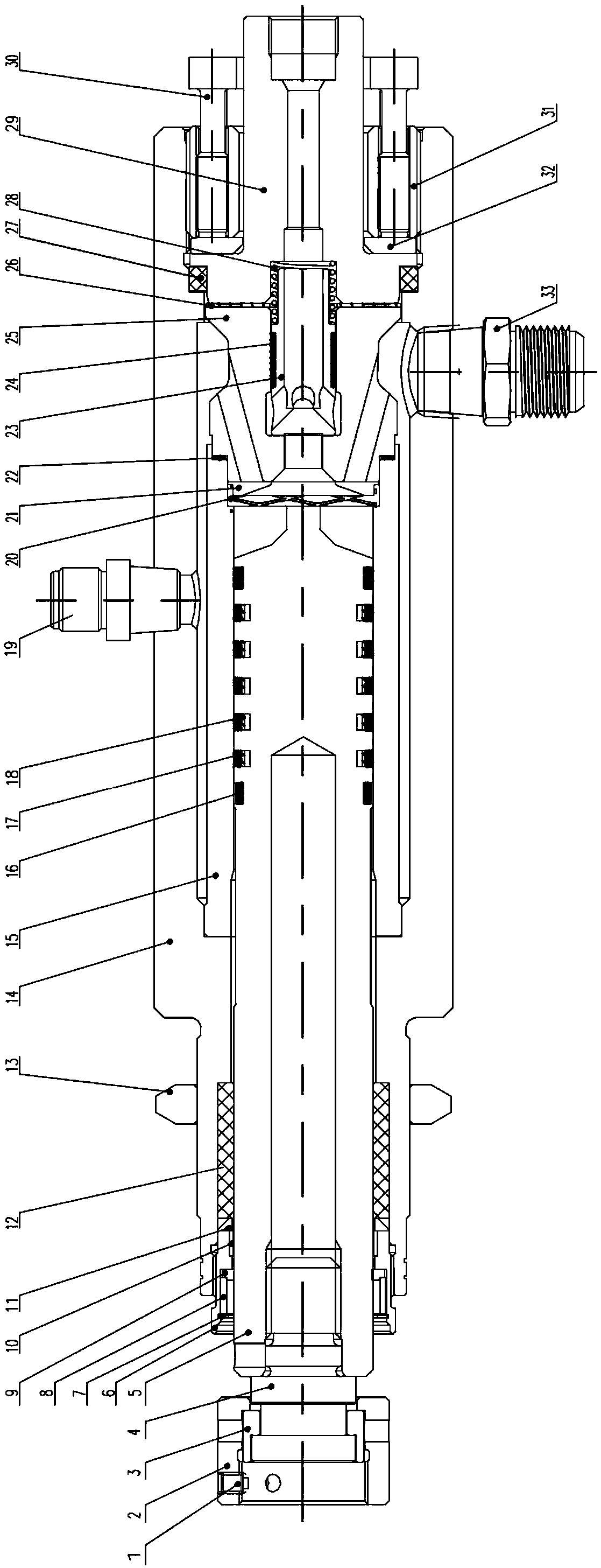
[0024] A cold end of a low-temperature high-pressure plunger pump includes a cold end housing 14, a plunger 5, and a cylinder liner 15. The plunger 5 is arranged inside the cylinder liner 15, and the cylinder liner 15 is located inside the cold end housing 14. The front end of the housing 14 is provided with a connecting and locking device. The cold end housing 14 includes two mutually connected cavities on the left and right. The right end of the plunger 5 is inserted into the cylinder liner 15, and the left end of the plunger 5 passes through the left The cavity body extends out of the cold end housing 14. The left cavity body is equipped with a seal around the plunger. The right cavity body includes a cylinder liner 15, a valve block and a discharge flange 29. The valve block includes a valve seat 25, The high-pressure valve 23 in the valve seat 25 and the low-pressure valve 21 installed between the cylinder liner 15 and the valve seat 25. The center of the valve seat 25 is p...


PUM


Abstract

The invention belongs to the technical field of low-temperature high-pressure plunger pumps, and particularly relates to a cold end of a low-temperature high-pressure plunger pump. The cold end comprises a cold end shell body, a plunger and a cylinder sleeve, wherein the plunger is arranged inside the cylinder sleeve, the cylinder sleeve is located inside the cold end shell body, a connecting locking device is arranged at the front end of the cold end shell body, the cold end shell body comprises a left cavity and a right cavity which communicate with each other, the right cavity internally comprises the cylinder sleeve, a valve set and a discharging flange, and the valve set comprises a valve seat, a high-pressure valve arranged in the valve seat and a low-pressure valve arranged betweenthe cylinder sleeve and the valve seat. According to the cold end of the low-temperature high-pressure plunger pump, the novel valve set structure adopts metal sealing, continuous opening and closingof the high-pressure valve and the low-pressure valve are achieved, and normal-pressure ultralow-temperature liquid nitrogen is converted into high-pressure low-temperature liquid nitrogen and is discharged so that the requirement for high-frequency opening and closing can be met, the characteristics of being low in conveying medium temperature and high in output pressure are achieved, and the problem that a common plunger pump cannot pump the low-temperature and high-pressure liquid nitrogen is solved.

Description

Technical field [0001] The invention belongs to the technical field of low temperature and high pressure plunger pumps, and particularly relates to a cold end of a low temperature and high pressure plunger pump. Background technique [0002] Liquid nitrogen pump is one of the commonly used equipment in oil and gas drilling and production operations, mainly used for fracturing accompanied injection, gas lift or replacement operations; the compressed nitrogen directly generated by ordinary air separation nitrogen production equipment can only produce a maximum discharge pressure of 35MPa , It is difficult to meet the fracturing requirements of oil fields, and how to generate high-pressure nitrogen has become a problem. Since liquid nitrogen is an ultra-low temperature liquid with a boiling point of -196°C, it is very sensitive to temperature. Due to the physical characteristics of liquid nitrogen and the special process of liquid nitrogen, traditional media injection equipment, suc...

Claims


Application Information

Patent Timeline
IPC IPC(8): F04B53/10F04B53/14F04B53/08F04B53/00F04B15/08E21B43/26E21B43/12
Inventor 菅保国李朋
Owner YANTAI JEREH PETROLEUM EQUIP & TECH CO LTD
Learn More