
Cloth rolling device for chemical cloth fabric

A cloth fabric and chemical fiber technology, which is applied in the field of cloth rolling devices for the production of chemical fiber fabrics, can solve problems such as disordered cloth rolling, single structure of the device, and easy shaking, etc., achieve safe and convenient use, scientific and reasonable structure, and solve the disorder of cloth rolling Effect

Inactive Publication Date: 2019-03-01
长兴一盛纺织有限公司
View PDF13 Cites 3 Cited by
  • Summary
  • Abstract
  • Description
  • Claims
  • Application Information

AI Technical Summary

Problems solved by technology

[0004] The present invention provides a cloth rolling device for the production of chemical fiber cloth fabrics, which can effectively solve the above-mentioned background technology. For example, a Chinese patent discloses a cloth rolling device, and the authorized announcement number is (CN 102452566 A). The roller is wound on the rotating shaft, and the roller reaches the rotating shaft, so that the dyed cloth can be wound on the rotating shaft accurately and neatly, which solves the phenomenon of disordered cloth winding in the traditional cloth winding machine, but the device has a single structure and cannot be set up. Reasonable, when operating, the device is not stable enough, it is easy to shake, and the effect of the device for rolling cloth is reduced. Secondly, it needs to manually pass the cloth through the roller every time the cloth is rolled, which is time-consuming and laborious, and it is not easy Problems with mass production

Method used

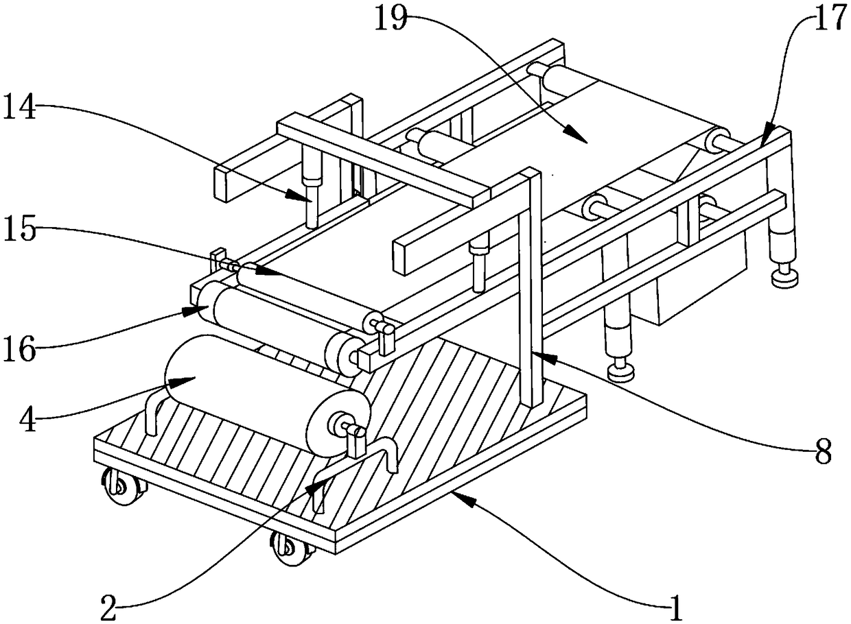
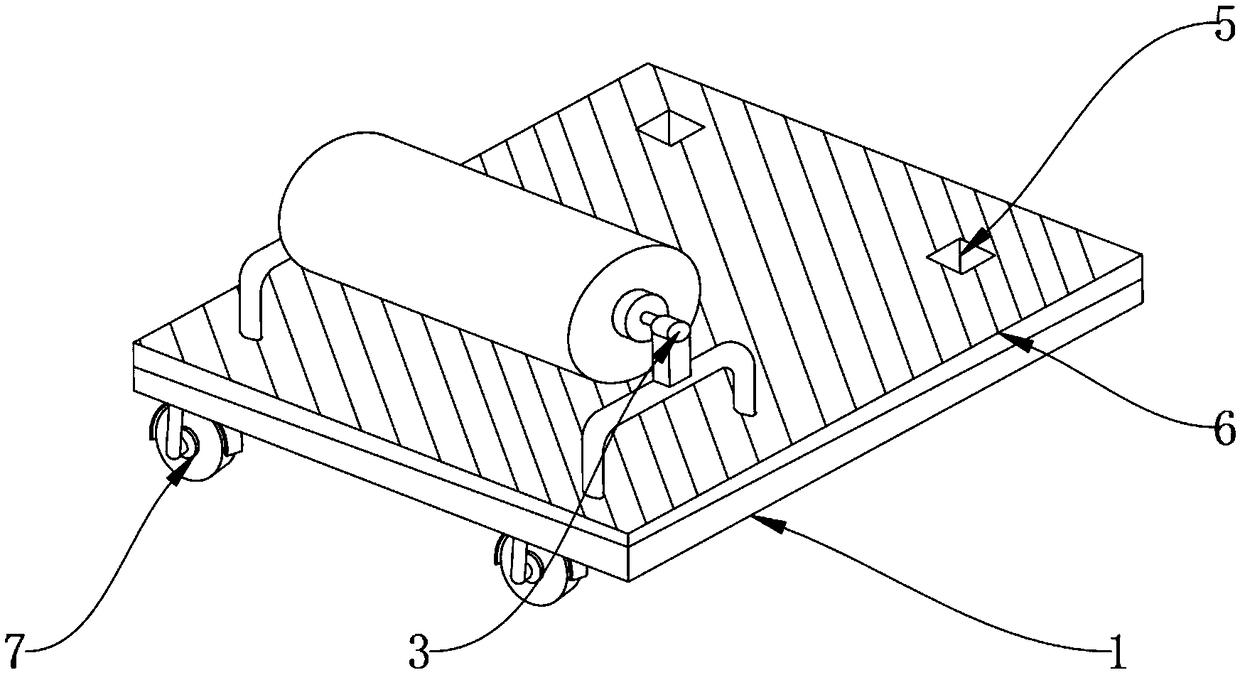
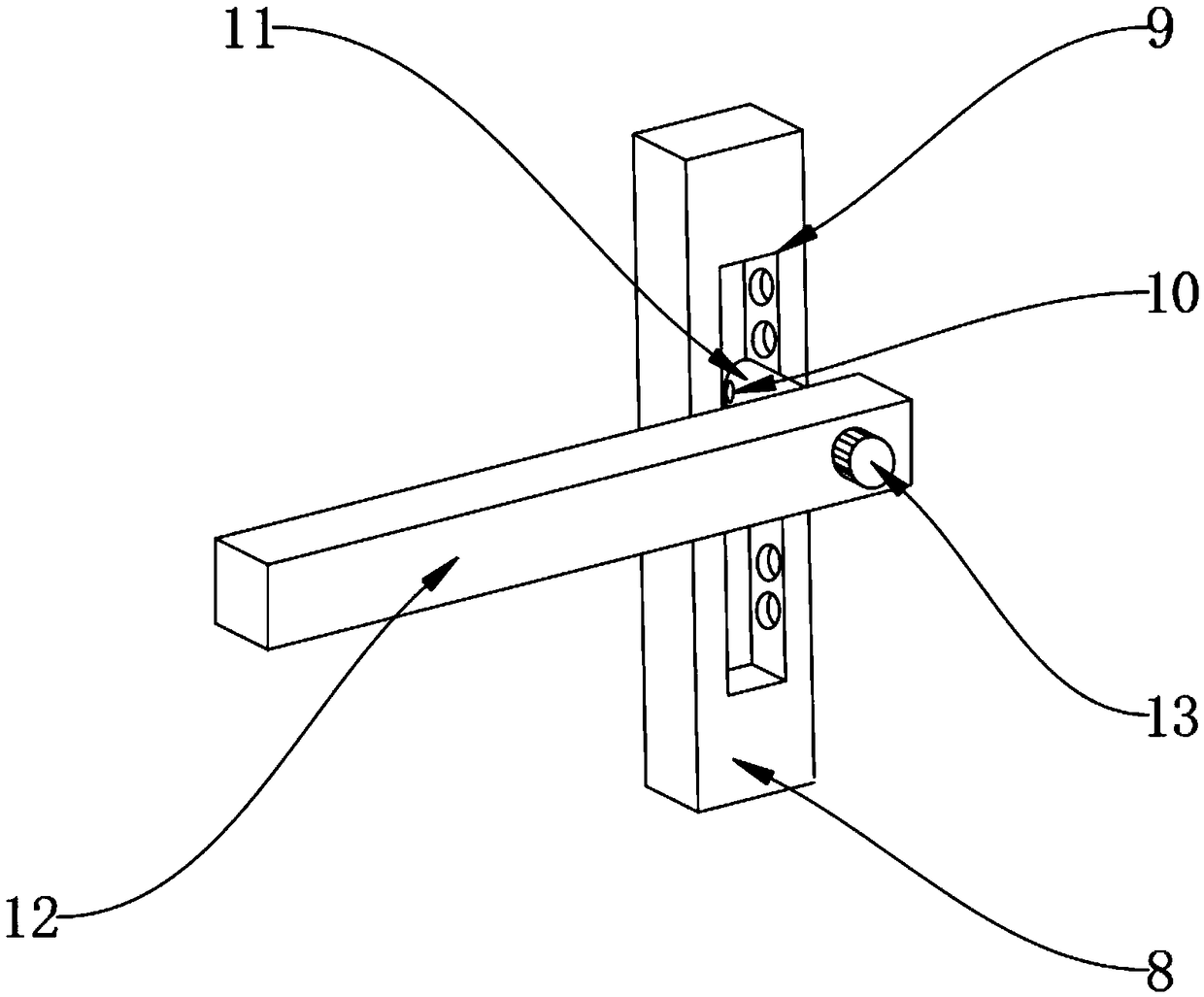

Image

  • Cloth rolling device for chemical cloth fabric
  • Cloth rolling device for chemical cloth fabric
  • Cloth rolling device for chemical cloth fabric

Examples


Embodiment Construction

[0023] The preferred embodiments of the present invention will be described below in conjunction with the accompanying drawings. It should be understood that the preferred embodiments described here are only used to illustrate and explain the present invention, and are not intended to limit the present invention.

[0024] Example: such as Figure 1-4 As shown, the present invention provides a technical solution, a cloth rolling device for the production of chemical fiber cloth fabrics, comprising a bottom plate 1, a first bracket 2 is installed on the top side of the bottom plate 1, and a fixing sleeve 3 is installed on the top of the first bracket 2. One side of the cover 3 is equipped with a first rotating shaft 4, the top surface of the base plate 1 is provided with a groove 5, a shock absorber 6 is installed on the top of the base plate 1, and universal wheels 7 are installed around the bottom of the base plate 1. When it is moved to a suitable position, it is fixed. One s...


PUM


Abstract

The invention discloses a cloth rolling device for a chemical cloth fabric. The cloth rolling device for the chemical cloth fabric comprises a bottom plate, wherein a first support is arranged on oneside of the top end of the bottom plate; a second support is arranged on the other side of the top end of the bottom plate; and a fixed rod is arranged on the surface of one side of the second support. The cloth rolling device for the chemical cloth fabric provided by the invention is scientific and reasonable in structure, and safe and convenient to use; through the functions of the bottom plateand a groove, the first support and the second support are conveniently fixed, and the occurrence of the phenomenon that a cloth rolling device with a traditional structure is easy to shake due to instability when being adopted for cloth rolling is avoided; by utilizing the functions of a rotary knob and a lock pillar, a sliding block sliding to the appropriate position can be conveniently lockedand fixed, and the occurrence of the phenomenon that when the number of dye cloths winding on a first rotary shaft is increased and a connecting rod upwards moves through a piston rod, the other end of the connecting rod cannot be fixed is avoided; and through the function of a conveyor belt, the chemical cloth fabric can be conveyed conveniently, so that the occurrence of the phenomenon that thecloth is enabled to pass through a roller shaft by manpower during cloth rolling every time is avoided.

Description

technical field [0001] The invention relates to the technical field of cloth processing, in particular to a cloth rolling device for producing chemical fiber cloth. Background technique [0002] Cloth rolling machine, which is used for various fabrics, non-woven fabrics, foam, leather, paper, reflective materials, acetate cloth, reinforcing tape, conductive cloth and other materials before rolling and packaging and various fabrics. Repeated rolling, can be rolled into straight or 45-degree twill fabrics, photoelectric side-to-side, can effectively align and automatically control codes for thick and thin materials, and can set the length of the roll. Humans use traditional methods for spinning and weaving. With a history of more than 2,000 years, spinning and weaving machines designed according to traditional principles are still the main equipment of the world's textile industry; [0003] For example, the Chinese patent discloses a cloth rolling device, the authorized annou...

Claims


Application Information

Patent Timeline
Patent Type & Authority Applications(China)
IPC IPC(8): B65H18/08B65H20/06B65H20/02
CPCB65H18/08B65H20/02B65H20/06
Inventor 张辰罗冬英
Owner 长兴一盛纺织有限公司
Learn More